|
LUXMAN
vintage
audio |
|
LUXMAN
vintage
audio |
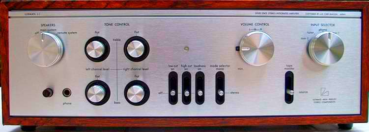
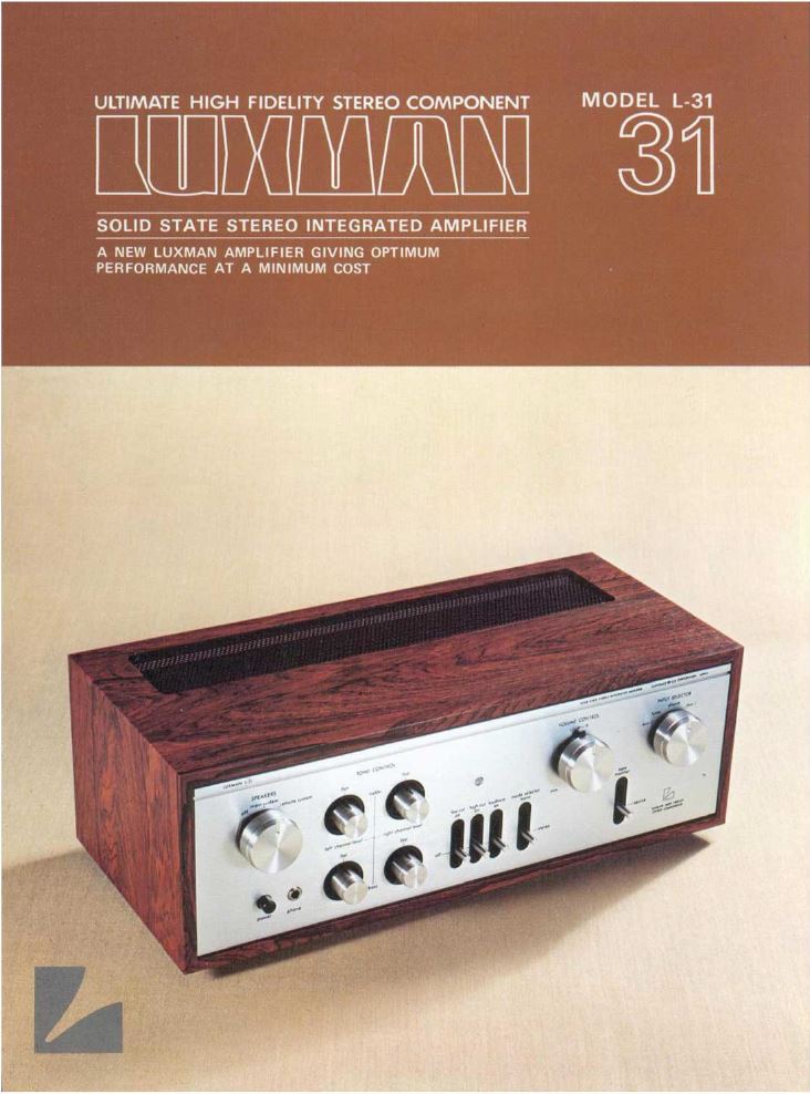
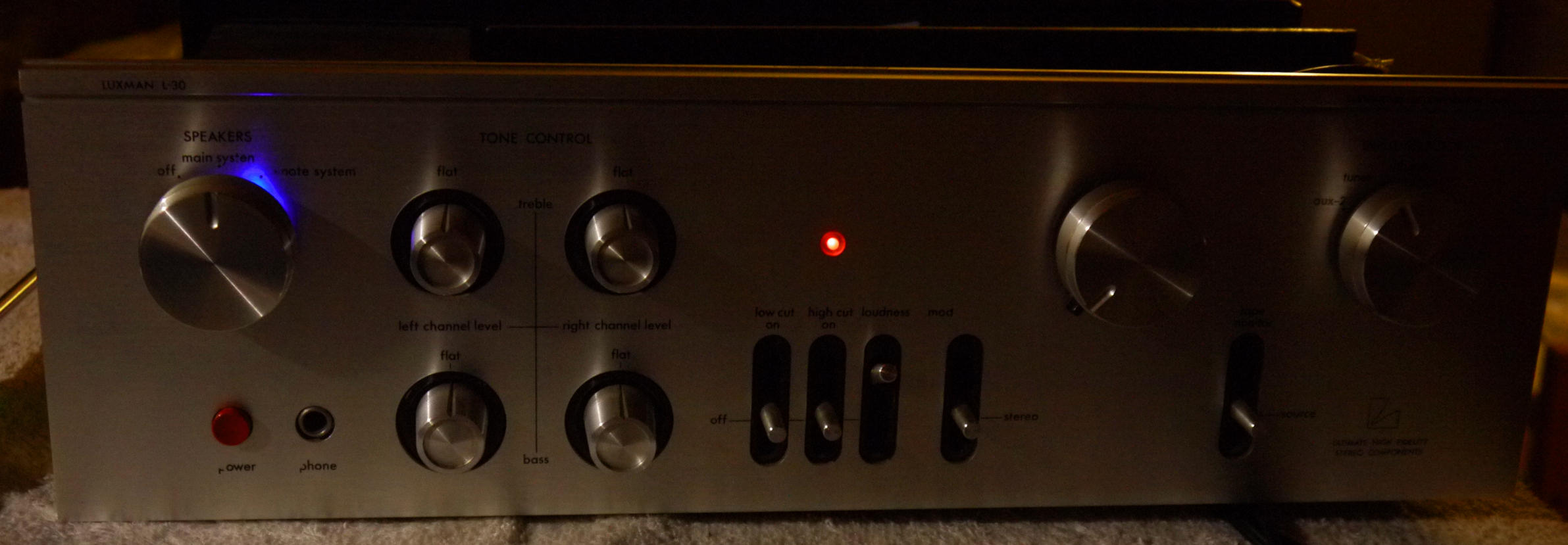
Luxman L30 & L31 integrated amplifier
General:
This is the very nice sounding 2x38 Watts L30 integrated amplifier from Luxman.
Its looks nice, it sounds good and it was relatively cheap and well constructed.
After a few years it was replaced by the L31, that was basicly the same amp with a little more Watts in the output.
User Manual:
not yet available
Special futures:
On higher efficiency speakers it was clear that this relatively simple amp was capable of delivering very good sound.
It has no major flaws in the design and construction. It has channel separated tone controls, like its bigger brothers.
Its very rewarding to extend the life of this amp by repairing and upgrading it to modern standards.
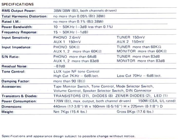
Specifications:
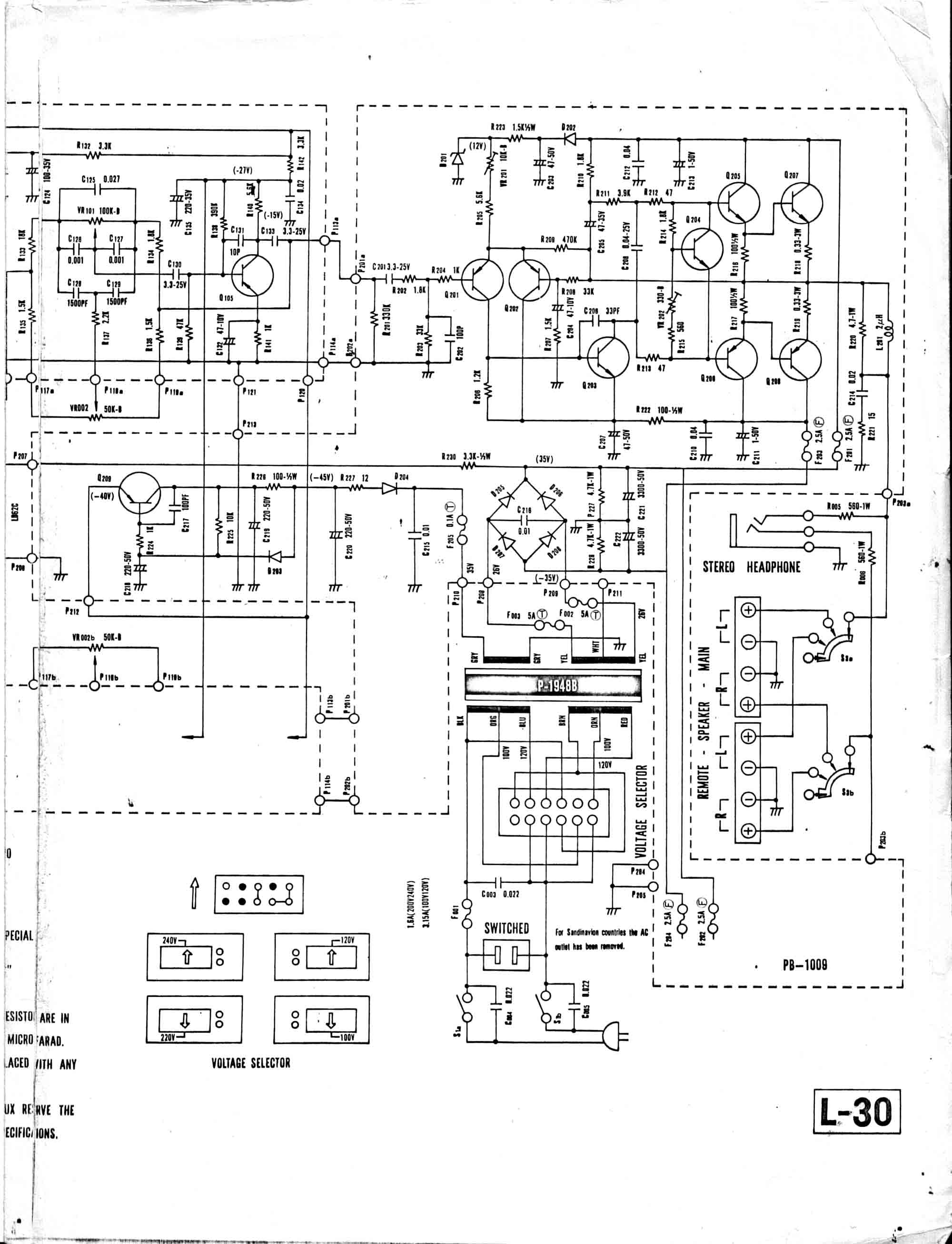
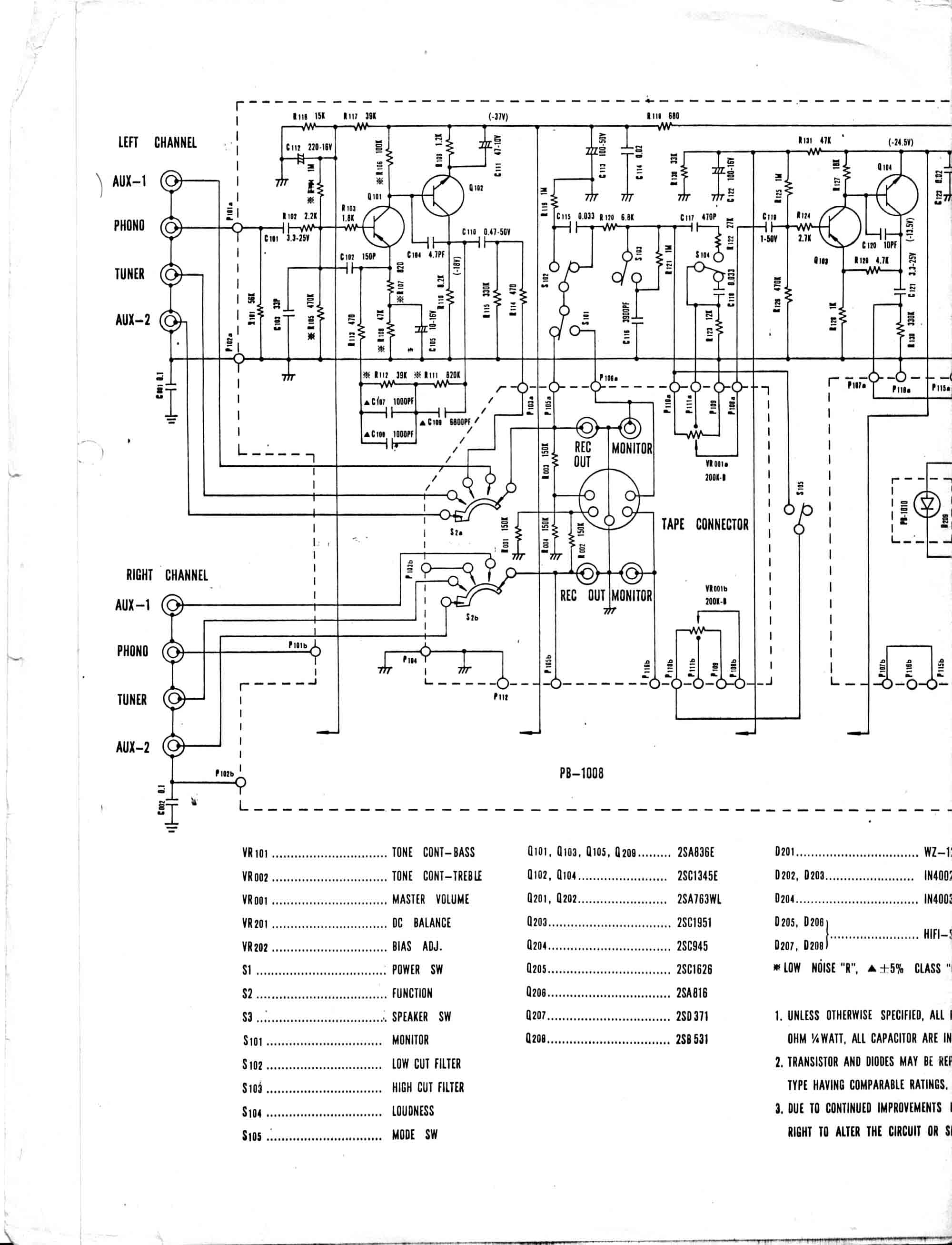
Schematic:
Service Manual:
The Service manual of the Luxman L30 amp, click here to download in Zip format.
Power amp section ^
Modifications:
Of course you can modify this amp to modern standards. Serviceability of the L30 is not great, but it can be done.
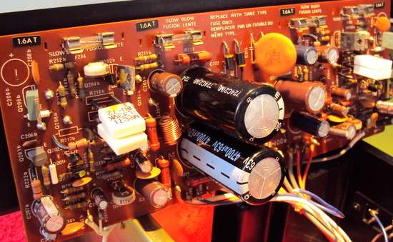
You may end up with a very sweet sounding amp, that meets modern standards and may give 45 Watts per channel.After alignment, one starts with the capacitors of the complete amp. Replace them for modern ones.
Insert a speaker protection pcb if you like *. Hardwire the speaker switch if you like.
The power supply can also be upgraded with better capacitors. use 2x 4700 or 10.000 uF 40V minimum.
and better (faster or higher current) diodes if nessecary at higher capacitance.
Check and adjust zero voltage and idle currents in the power section.Further modifications of the Luxman L30 can be the below parts that may be upgraded:
Only parts of LEFT channel are marked here, upgrade the RIGHT channel-amplifier as well, parts are marked A & B.
Power amp section: You may:
Change C211 and 213 into 100 uF same voltage, or higher.
Change C203 and 207 into 100 uF SQ (or LL or LN quality) same voltage or ^.
R201 to 206 can be metalfilm same wattage.
Add to C203 and 207 a capacitor of approx 0.047 uF 100V, (parallel to these electrolytic caps).
C201 can be small polypropylene 100V.
Power supply section:
Change C219 and C220 to 1000 uF same voltage.
Add to these C219 and C220 caps parallel a small capacitor of approx 0.047 uF 100V, same procedure as above.
Pre-amp section:
C130 can be small polypropylene.
C124 can change into 1000 uF SQ same voltage or ^.
C135 can change into 1000 uF SQ same voltage or ^.
C113 can be 1000 uF SQ same voltage or ^.
C119 can be small polypropylene 100V.
In the riaa pre-amp are already LN resistors placed by Lux, some R's in the signal path can be changed to metalfilm R's as well.
Thats all for the passive parts. Now the active ones:Replace all Hitachi small signal transistors, as they suffer from the notorious silver-oxide creeping disease.
The 2SA836 and 2SC1345 made by Hitachi will sooner or later add a lot of noise and even storm and thunder to your RIAA amp.
The Hitachi transistors will not survive, so you better start replacing now, other brands like NEC or Toshiba may be ok.
Replace with modern BC550C/BC560C (not pin compatible) or 2SA1015/2SC1815 (pin compatible) and all noise problems are history.
Remember that the Luxman PCB's are very delicate when you start desoldering.
Small signal transistors that are in this amp of other brands do not need replacement as they do not have silvered but tinned leads.
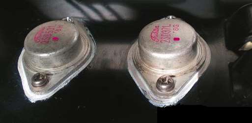
The power transistors in this amp are very good, made by Toshiba, if you have to change a set of these use
the original 2SB531 & 2SD371 or equivalents, or plastic NEC's or Sankens 2SC4466 or 2SC5100 and its complementary.
There are more equivalents of other brands, NOS or new. Apply new thermal grease.
If you can find NOS TO-3 transistors thats even better, as TO-3 transistors have better heatsink characteristics and
a better power transfer graph than plastic transistors, if you want to use the faster RET or LAPT by Sanken,
remember to insert extra anti-oscilation C's in the power-amp section, as these transistors
may have Ft's up to 60 MHz (!), the Toshiba's go only up to 10 MHz.
http://www.sanken-ele.co.jp
Toshiba original transistors ^
Speaker protection modification:
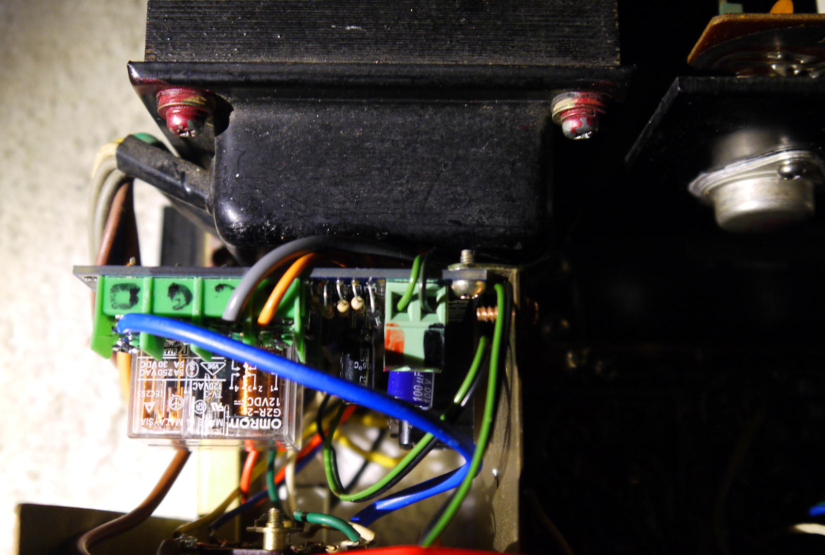
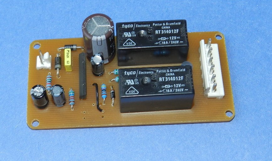
* Below you can see a more recent modification I made to my L30: Insertion of a speaker protection pcb. As the L30 has no speaker
protection circuit incorporated, its wise to buy a small kit and insert it into the L30, speakers can be very expensive and you do not
want to blow your speakers by a defective L30.
Behind the speaker selector switch S3 a/b there is enough space to put the speaker protection pcb in the L30 amp.
Also the pcb is sitting near the speaker selector switch, that makes it very simple to connect it properly into the L30 circuit.I used this: it fits very well as you can see on the photo above.
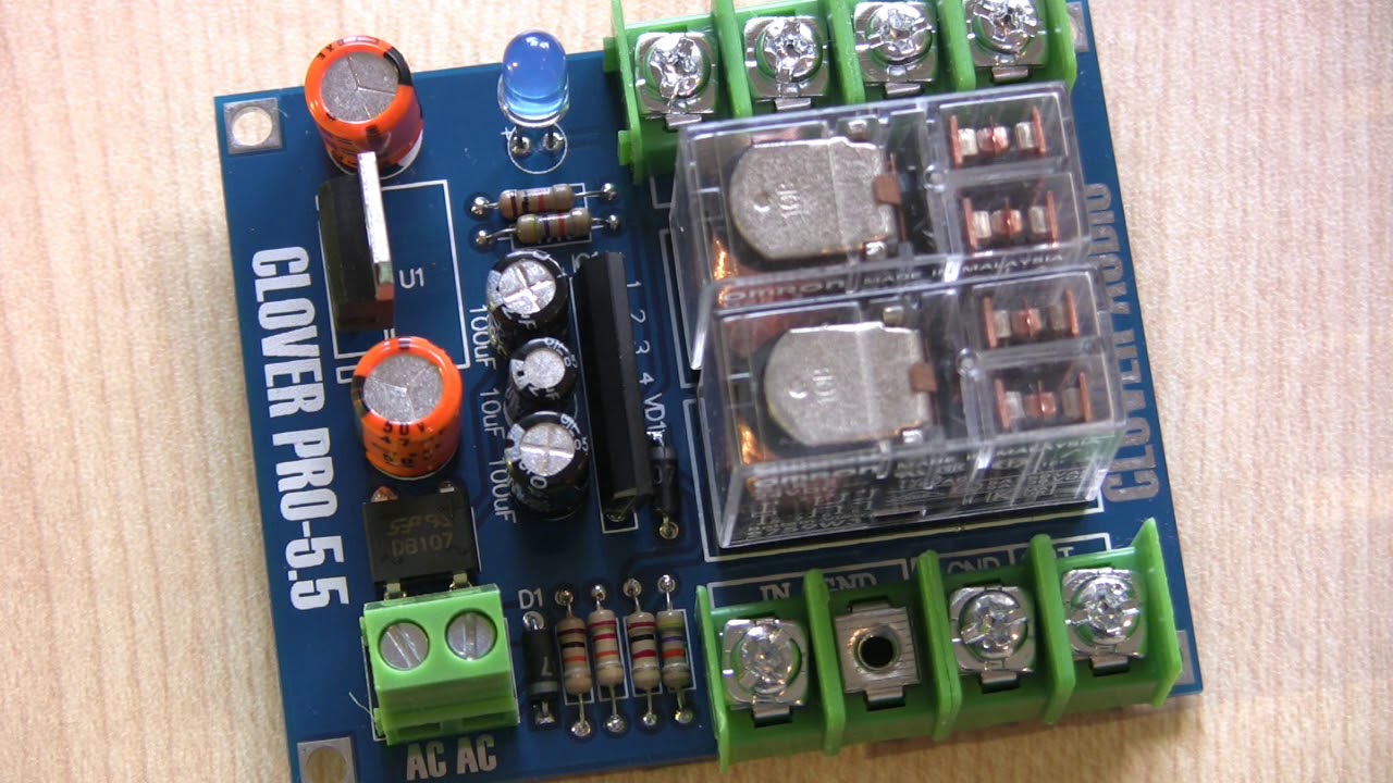
This is a smaller pcb employing the same IC, that works also very well:
The blue led that came with the pcb kit, I have inserted behind the speaker selector switch, then you are able to see if the
speakers are conneced to the amp and all is well with the amp: the circuit on the speaker protection pcb
senses the DC voltage level on the outputs of the amp, that should be 0 Volts. it goes only on when the voltage is ok.
You do not have to make changes to the L30 as the amp stays in original condition.
Looks nice not?
Sound:
The L30 is a very good, extraordinary sounding amplifier. The combination with Tannoy HPD 295A or HPD315 is excelent.
Take a look at the Tannoy Monitor Gold website for more info on Tannoy speakers.
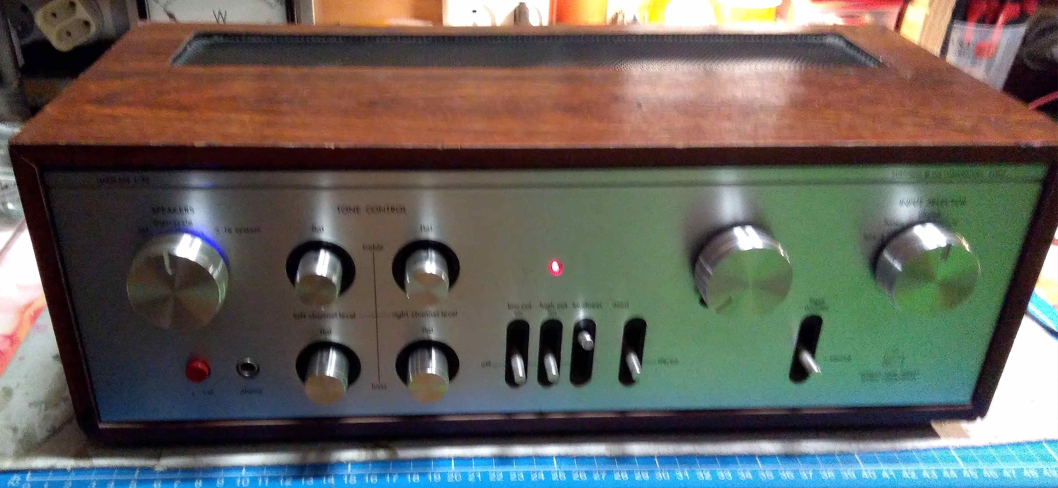
New tone knobs ^
Links:
here another interesting read about the restore of a L30/31:
http://blog.brahm.ca/2018/06/rebuilding-1977-luxman-l-30-stereo.html
![]()
![]()
© Hans Hilberink - PE1MMK ® & Ruud 2003/2023 - Last update: 10-09-2022.