by John Ridley
Part I
Preface
Hi, this is not a project, rather a diy constructional guide/assist.
No readymade PCB's are available or layout suggestions are implied... other than normal proper procedures/precautions, as star configuration earthing, ps wiring, and bypassing. Input and output shield's should be earthed to the chassis as close to the input and output sockets as is possible. Clean or signal ground connections then should be made from the power supply common/bus in star configuration, with low power supply impedance and the usual two levels of hf bypassing. Today many of the better sounding IC's are surface mount devices rather than conventional minidip. Conversion headers smd to minidip are recommended,
available here.The Active Crossover
Correspondence to hand from Alex Garner of Tannoy (1997) kindly forwarded by Pierre Buckens (IEEE) states .........
"if one were to determine the filter responses of the passive networks in place, for example, in an Tannoy XO5000/M3000 module then one would have all the information needed to duplicate an active (crossover) system. He states further that the voltage (drive) responses of the Tannoy passive crossover network are complex, and cannot usually be synthesised with simple filter concatenation, but once the active/passive analogue circuitry is designed it will sound better than the passive network although it takes much longer to design and is far more complex."
end
The Tannoy passive filter responses (which are ideal responses) are available from Hans' site under the title "Software Simulation of Red and Gold crossover response"
here..........
http://www.hilberink.nl/codehans/tannoy84.htm
The circuit used for these, the original 1967 passive crossover, is on Hans' site also,
here
http://www.hilberink.nl/codehans/tannoy37.htm
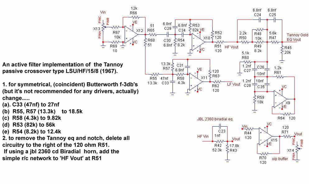
In graphing the original passive crossover, it is seen that the HighPass and LowPass f-3db frequency assymmetry and initial slopes are Tannoy's own (variation of) 2nd order filter, empirically determined and complementary to the characteristics of the Gold's drivers, quite definitely not to conform to a textbook Butterworth (or a textbook anything else, in keeping with most all other high quality custom/purpose designed crossovers).. Then follows shelving and unique frequency compensation circuitry.
the active circuit's curves track closely the original passive crossovers inbuilt (and necessary) frequency response compensation required for the Tannoy Monitor Gold, and at the same time improve the action of the notch filter.(see notes following graph #2)
Graph #1
Tannoy gold active crossover circuit diagram
.
Graph #2
The original Gold's crossover slopes (red traces) are overlaid with the Active's slopes (blue traces)
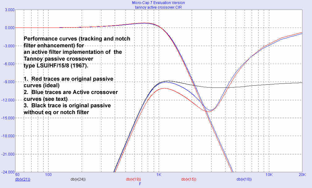
The topmost trace is the passive (red) LP filter slope, with the active (blue) crossover trace blending/tracking this.
The lower traces are the passive (red) HP filter section, with the active (blue) crossover trace tracking this, (albeit within the limitations of using standard prefered values of R and C.
of course the passives components are modelled ideally, in practice the passive network would be hard pressed to be within even +/- 5% of the idealised (red) curves themselves, actually.
The separate black trace is that of the passive HP filter section before the 3khz filter, for reference and as a reality check.
In the original Gold's passive crossover, the 3khz notch filter cannot cure the drivers inherent ~3khz resonance anomalies, (tannoy honk) it can only attempt to reduce the excitation of the resonance(s) by actually preventing similar frequencies (tone) in the composite audio intelligence (music) from actually getting to the driver. IE by taking out part of the music on either side of the resonance as well as those tones with similar frequency to the resonance,
In preserving the original filter's passive sonic characteristics, 'Q' and notch depth, improvement of the 3knz notch symmetry about the centre frequency has been made, (blue trace), allowing about 1.25db more detail for over an octave of the important midtones preceding the notch.
The active crossover is maximally flat, ie no treble rolloff is provided, there is no provision for the originals switched degrees of treble cut.... it is felt that if this is required the preamplifier curves are far better suited to the task. The shelving or so called Treble Energy coarse switching of the original is likewise far more finely implemented by the final/power amp volume control.... as well, this arrangement reduces needless amplification of the preceding stages noise floor/hum ).
Many past active filters use opamps strapped as voltage followers in conventional Sallen and Key filter configurations. However, we can do much better in terms of lowering high order, high frequency distortion performance in eliminating the common mode signal, by using the inverting configuration to realise the Rauch, or mfb topology.
-one can use any audio circuit/gain block/opamp capable of directly driving a high capacitance load with stability, and at line level into 600ohms, ( but which precludes use of many opamps like the TLO72, AD744 etc).
it is recommended to choose IC types from the following short list.
-at least to the standard of the old 5534, OP27, but the more recent Burr Brown OP627, the National LM6172, the AD 843 used by Schaefer in their excellent pre/pwr amplifiers, the Analogue Devices AD825, but preferably the new AD-8065 and AD-8610 which have more midbass and bass punch than the Burr Brown OPA627 (the AD types can be wired to minidip headers, to which have already been soldered the capacitive load isolating 120 ohm resistors and miniature 0.1uf bypass caps across the power supply pad/pins).
As with thermionic valves, there are relatively few IC's possessed of really excellent neutral and 'grain' free sonics, of which small group a favourite is the relatively new 8610 or the 8065 types ic, which has rapidly gained critical acceptance due to its excellent subjective performance.
-It demonstrates extremely detailed, neutral lows, mid's and high's with excellent bass 'punch' but is 'grain' free, even when not too much care is taken wrt power supply filtering. (this ic was purpose designed by a team at Analogue Devices with these subjective attributes foremost. The chip is intended as a nocompromise i/v...(.the first analogue stage immediately after the dac in a high quality sacd player. (it is not intended for lowest noise apps like mc cartridge/ riaa front ends etc).
General Active Crossover advantages
Apart from the headroom and intermodulation aspects, advantages to the enthusiast for the active crossover may be foremost below, but not necessarily in the order following,(1)
That an amplifier type/topology can be optimally chosen for the frequency range utilised (SS or SET, etc) .....There is no doubt that a good SS amplifier affords most control over the area where the lf driver's impedance can vary from 5 ohms at upper mids, and up to 70 ohms or more at fs, for conventional bass reflex designs, let alone Rear loaded horns.
The impedance variation due to the mid driver crossover is quite significant as well, and introduces additional colouration to a greater or lesser degree, depending on the source resistance/fo (or output impedance characteristics) of the particular amplifier (which impedance varies greatly from mid to high fo's) driving the loudspeaker network. All amplifiers are freed from 'seeing' the additional reactance of the passive crossover otherwise employed.... it may be beneficial to employ a simple Zobel across any given amplifier output to secure a very uniform impedance for it to look into..
(2)
The low pass (series) inductor in the low frequency crossover section is eliminated, leaving only the length of copper wire in the wiring runs between the amplifier and loudspeaker system, which can be OFC, OCC or HCC copper wire, with each wire separated to reduce cable capacitance, and it's detrimental loading effects on many feedback amplifier types..
With respect to an lf drivers quite natural, and comparatively violent oscillation and blur contribution at self resonance, even for 'low Q' pro drivers like Tannoy, JBL etc, the maximum amplifier control attainable is largely negated by the DCR of the low pass filter's inductor in series with the lf driver voice coil.
Typically this measures 0.5ohm to 1ohm for a very good inductor with an iron core, while the speaker cable may be only <100mohms, while about 6 feet of 12 guage building wire used as speaker wire has a dcr of only 9 milliohms.
Air cored coils do exhibit less distortion than conventional iron cored, but it is very expensive to get the DCR down to the same values by using 0.8mm copper wire on very large coil forms.
Note that an SS amplifer output impedance contribution is typically only 40milliohms or even less for a very good SS like a Schaefer........a DF of 200 to 2,000 at mid fo's.
...... while for an SET without negative feedback it can be as high as 2 to 3 ohms. (df of 3 or 4)
SET enthusiasts may consequently restrict use of SET's with no global feedback to speaker systems with more uniform impedance characteristics than some examples of Rear Loaded horns.
Further considerations
Surprisingly, there is not so much a cost penalty for the additional (bi)amplifier(s) in many cases, when one consideres the Very Expensive outlay possible for silver foil inductors and exotic capacitor types used to modify the passive crossover, (which by the way, still leave the other passive crossover compromises mentioned above unchanged!).
The active filters use low cost small value <0.01uf styroseal (or polypropylene) caps. impedances were calc'd to suit a bunch of 6.8nf Styroseals for my bro-in-laws golds because they have excellent DA and sonics, are physically small and far less costly than most exotic types. (i also have a thousand or so in stock).
.
The active crossover as shown maintains i/o phase... IE + polarity signal input gives + polarity signal output.
-Only if a high impedance buffer exists at the input of the following stage(s) no additional buffer circuitry is required.... if not, use the unity gain high input z output buffer depicted, on each of the outputs.
if additional rf filtering is desired.....
Add 2.2k in series with the input volume control (10k) and
parallel the volume control (10k) with 1.0nf capacitor.........
ie the 2.2k resistor and the 1.0nf cap form a low pass filter at 100khz ... This gives a first f-3db at 100khz at the output of the tannoy eq filter.
The same f-3db can be introduced at the output buffer by changing R71 to 2.2k and adding 1nf in parallel across the 10k volume pot here as well.
An additional pole (f-3db) at 100khz is given by paralleling 150pf across the 12k R66
Note that the frequency dependent characteristics of the tannoy eq filter is very sensitive to capacitive loading of the output across R45 .
If it is intended that an interconnect cable's capacitance is to be present/needed from here it is imperative that the high impedance buffer is used at the tannoy eq filter output.
-only if the directly following inputs are hiZ buffers take o/p from:
highpass R45,
or for jbl 2360 Biradial R44.
lowpass R62
Other speakers
For those who own large format jbl drivers/cd horns, values are shown that result in Butterworth filter characteristics,
the simple jbl 2360 cd BiRadial horn power response correction network on the circuit diagram then substitutes entirely the Tannoy exponential correction circuit to the right of the 120 ohm R51.
(Note that jbl drivers do not require any preliminary EQ or the cd Biradial power response correction when used with exponential or tractrix horns).
John Ridley johnridley@tpg.com.au
© Copyrights Hans Hilberink & John Ridley, last update: 10-06-2004. Va.