Transistor Amplifiers
![]()
Schematics and photos of transistor amplifiers.
This page is under construction. More schematics & photos to come.
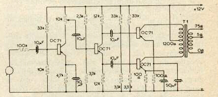
Above early European design of a transistor amplifier with early glass transistors OC71 made by Philips Holland in 1955, the transistors were hardly available. In 1958 the transistors were better available in the local radio component stores, but expensive. As you can see every stage is coupled to the next stage by a capacitor. Look at the four capacitors in the output stage, at the B and E of the OC71, how they made desperate efforts to avoid the use of a driver transformer that some years later was commonly used ! This amplifier was capable of delivering approx. 50 mW to the speaker.
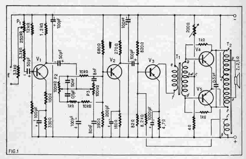
Below a French design of 1960, common in the 1950's and 1960's. It was more powerful compared to the first generation amps, it was capable of delivering some 10 Watts maximum as it has the first generation TO-3 (alike) final transistors: Philips OC16. The transformers were widely used in these days, but in the 1970's became obsolete as miniaturisation became an issue with transistor designs. And so these huge bocks of iron did not fit in the audio-picture anymore. Luckely sound quality was improved with iron less designs.
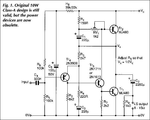
Below the original John Linsley-Hood’s Class-A power amp design, as you can see it is very simple and it employs only 4 transistors. OTL was a fact! This kind of amp finds its roots in the end of the 1950's. In the 1960's and later these amps were quite common. The advantage compared to earlier designs is de DC coupling of the stages and the OTL final stage. A huge improvement in sound quality as it turned out.
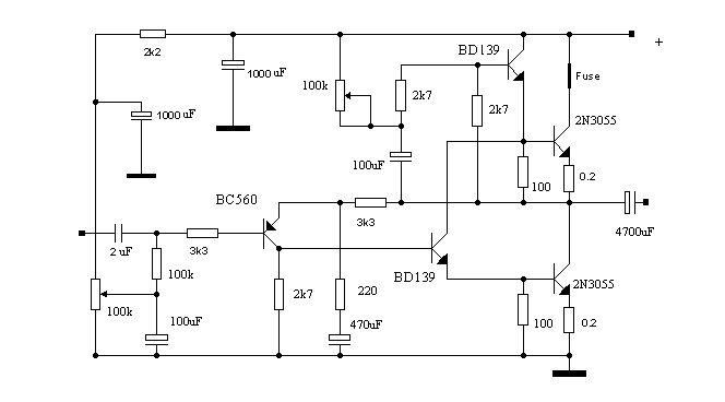
Below a 5 transistor variation on the above theme.
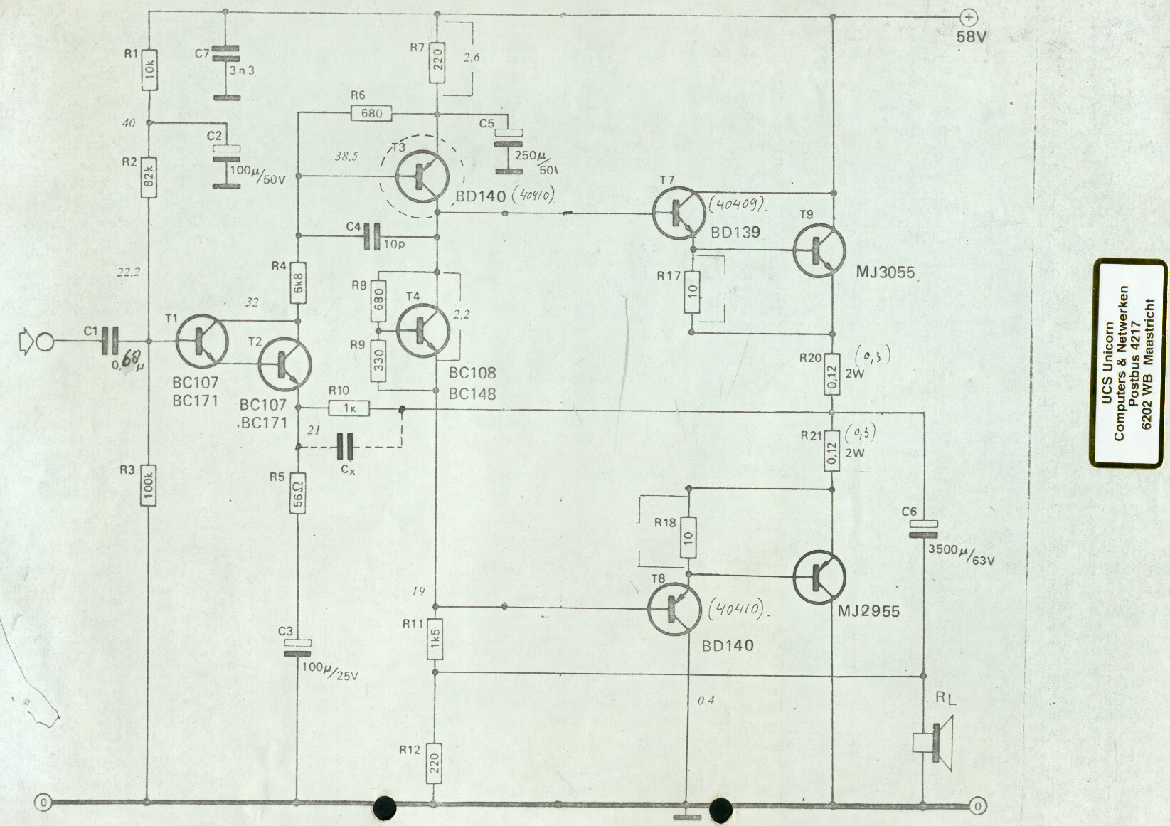
Below is an early simple amplifier (class AB or B design by PE1MMK, that is based on Quad designs) from 1969. It is a single power rail design as usual in those days. Performance was beyond the capabilities of the Quad 303 amp and sound was much better than the Quad and Linsley amps. As you can see some symmetry is introduced already in these amps. The input transistor is replaced by a darlington to keep up the input sensivity. This amp was capable of delivering a clean 40 Watts to the speaker. Feedback can be reduced by changing the value of the 1k resistor but stability and frequency response change, the capacitor Cx has to be determined in that case. The amp is still in use and its users are still content with it.
The advantages of this simple amp were: Complementary final stage that lowers distortion, the disadvantage is the single power supply rail. Again a step into the future.
Here a simplified experimental schematic diagram of the same kind of amplifier but with modified inputstage: a differential amp. input stage. The differential amp reduced noise and input inpedance could be applied with a simple resistor, also feedback can be reduced. Again a step forward. The application is by RCA, final release in 1972:
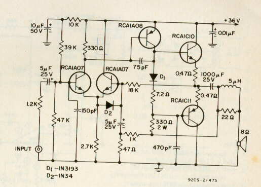
With the differential input stage a very nice amplifier is realizable:
Read on: Click here to goto page 2 of this section.
©Hans Hilberink PE1MMK 04-10-2001.