|
LUXMAN
vintage
audio |
|
LUXMAN
vintage
audio |
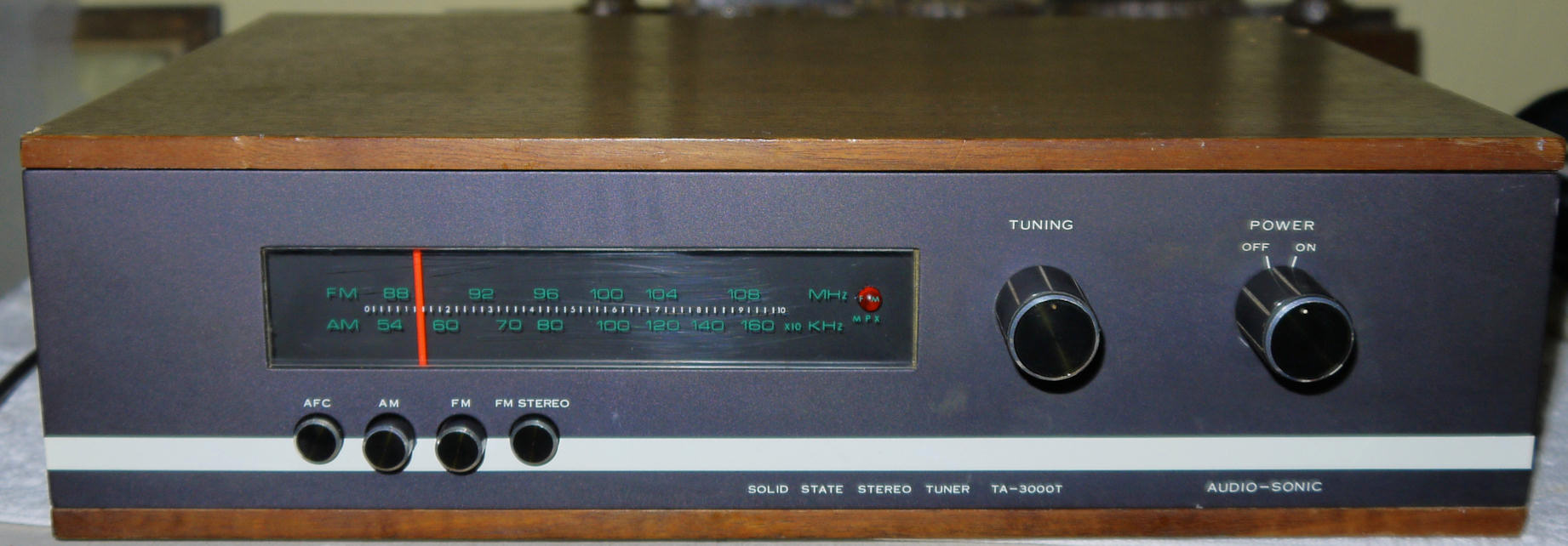
AudioSonic TA-3000T AM/FM Tuner
General:
Around 1968 issued tuner for European market, made for the 'Audio Sonic' company, by "Comet Electric Company" in Japan.
Front ^
Owners manual:
(not yet available)
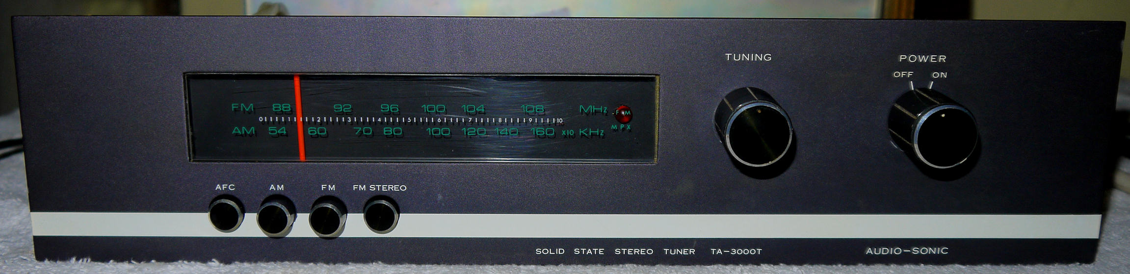
Front face plate ^
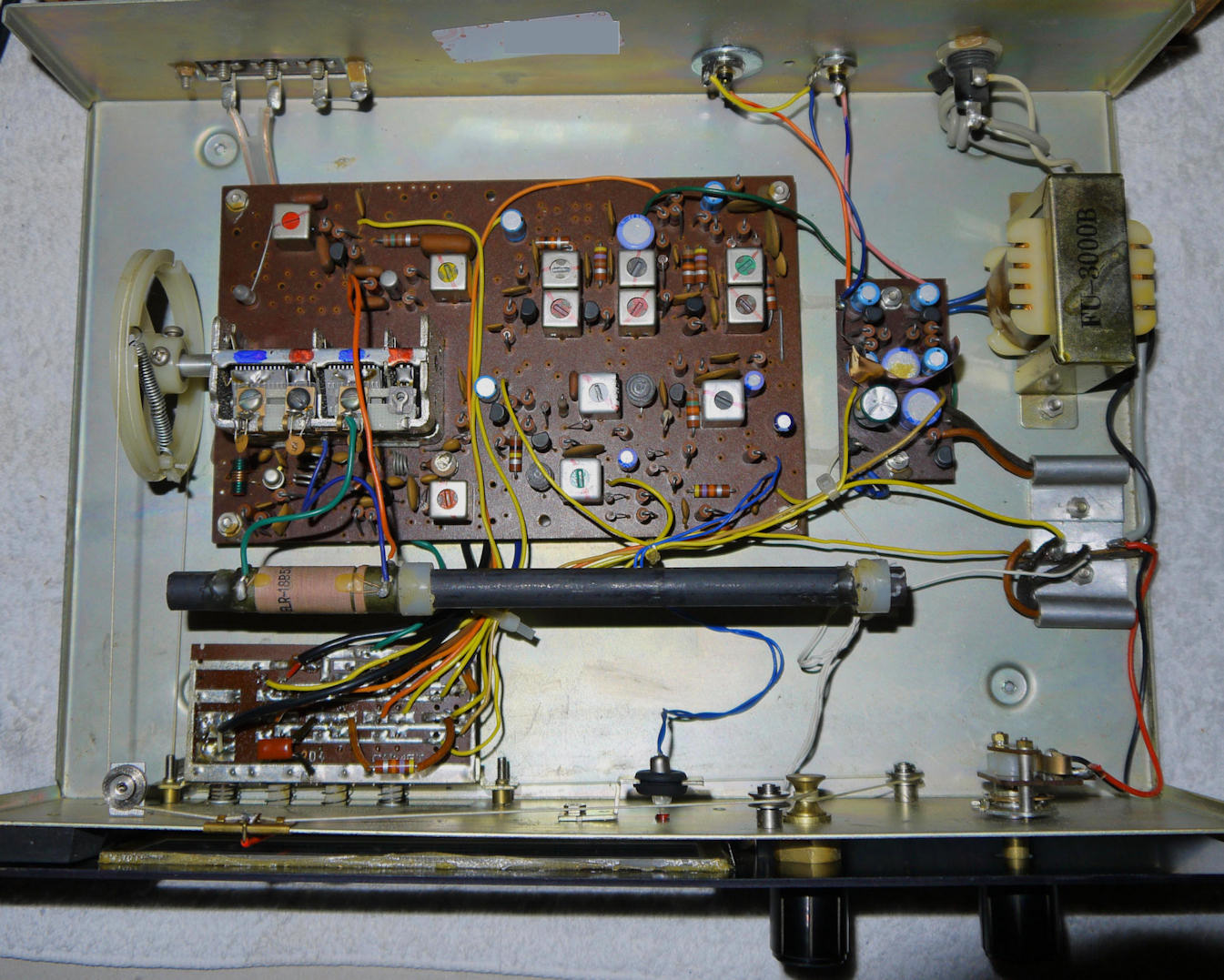
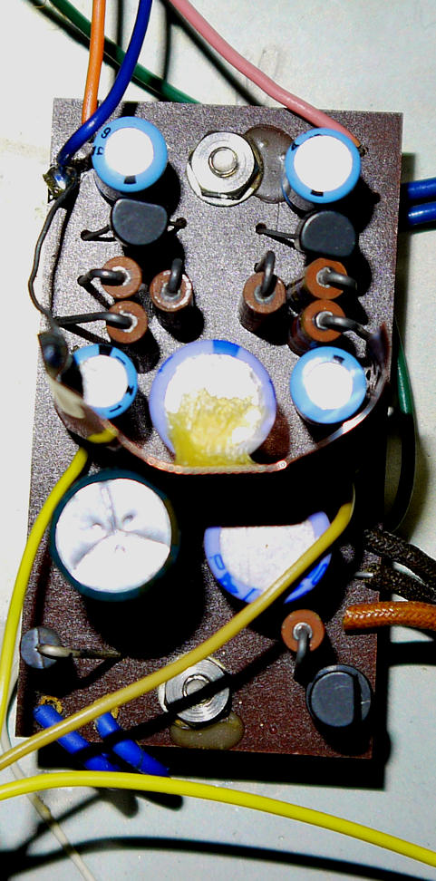
Interior, simple yet very well built and good pcb's used, remarkable simple power supply: 1 diode & 1 capacitor, photo made starting the update process ^
special futures:
This solid-state tuner is with DIN socket to be replaced by RCA output sockets.
Nice simple look tuner.
Wood case.
Well build and good parts used.
2 gang variable capacitor.
This tuner employs silicon and germanium transistors.
The tuner has a stabilzed power supply.
Traditional ratio detector, traditional MF section with coils.
AFC switch at the front, working and usefull.
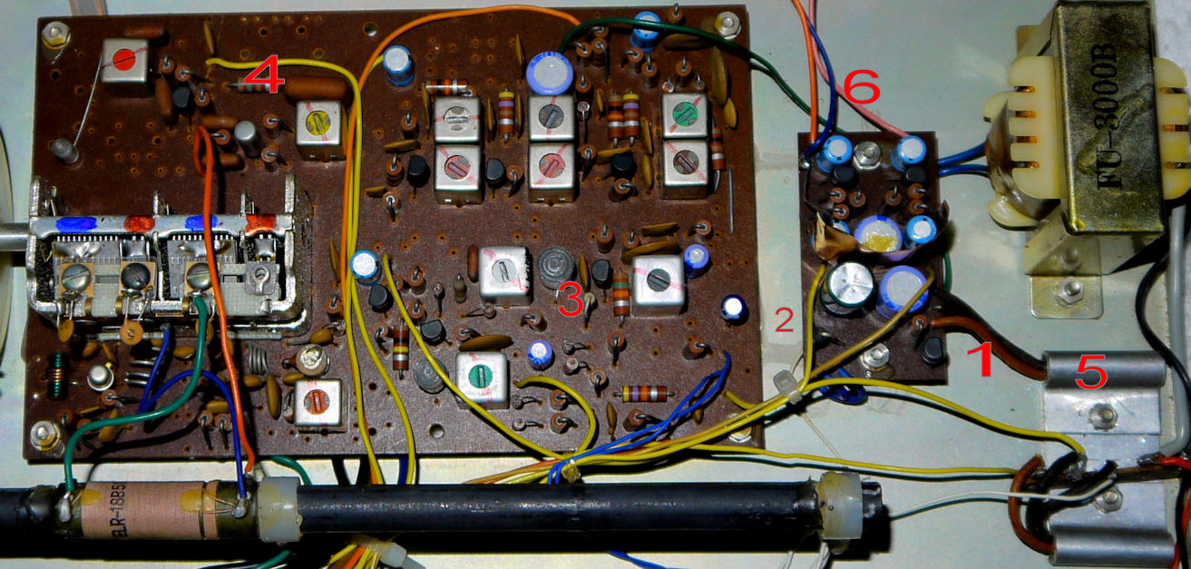
Interior with 6 marked sections:
1. Zener diode of the stabilization power supply part.
2. Single diode rectifier.
3. Simple MPX section.
4. 1 silicon and 1 germanium transistor in the AM section.
5. Germanium stabilizing transistor heatsinked for the power supply and one switching transistor for the MPX lamp.
6. Audio section with L & R transistor for final amplification on PS pcb board.
Power supply problems:
The detrimental power voltage change from 220 to 240V in the EU is no issue here: The tuner has a 240V transformer.
The rectifying in the supply section of the tuner is simple: only 1 diode is used, and only 1x 470µF capacitor.
This makes the tuner vulnurable to 50Hz hum.
I upgraded the secondary part of the supply to a rectifier bridge with 1 capacitor of 1000µF.
A few extra capacitors may be added to the power supply to get it to modern standards.
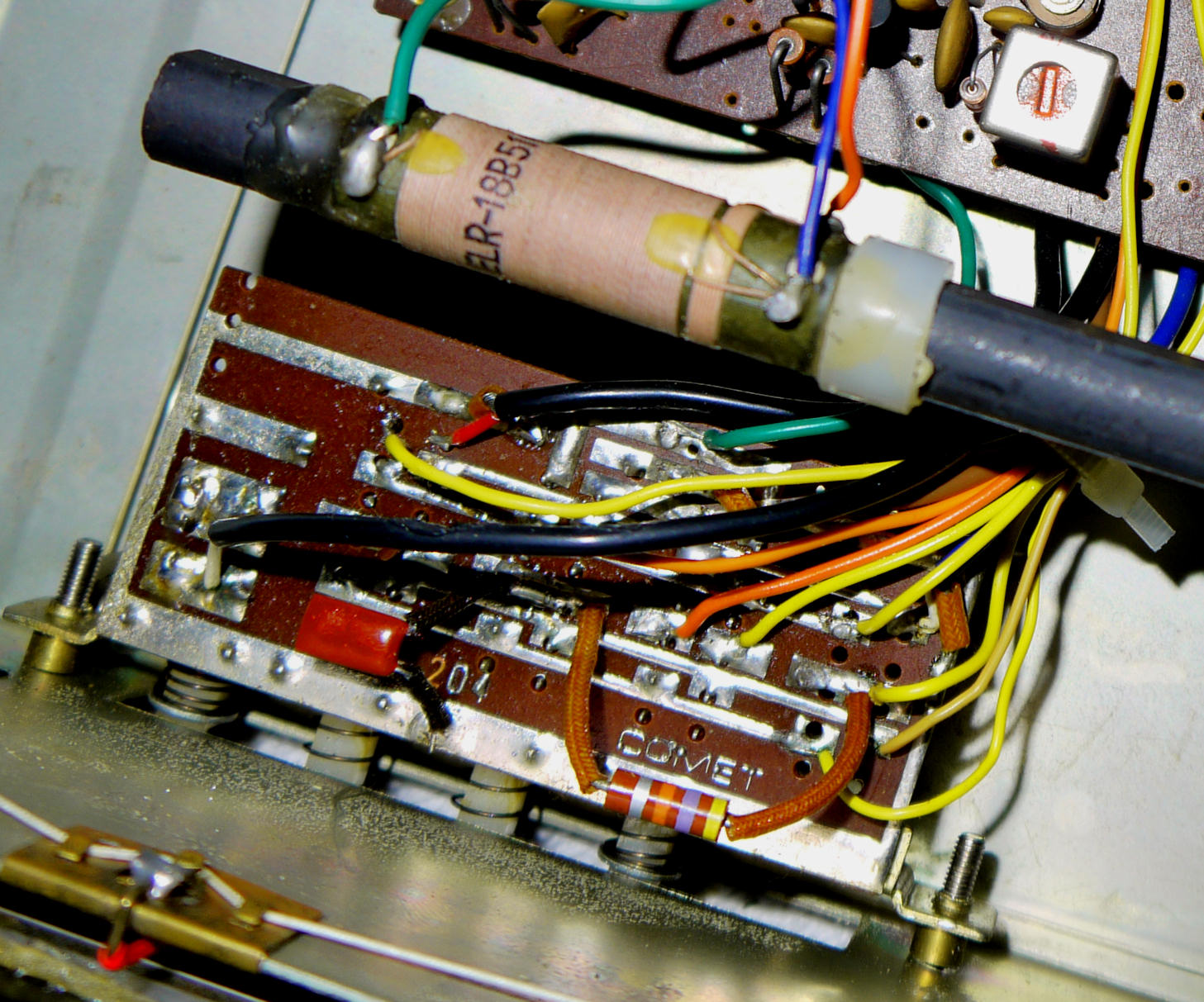
Power supply upgrade ^
AM antenna ferrit bar inside and switch pcb ^
Specifications:
FM IHF sensivity: 5 µV at 25 dB S/N.
Capture ratio 2 dB.
Distortion (THD 20Hz - 14kHz) ~2% at max input voltage.
Signal/noise ratio: 40dB stereo.
Channel spearation approx. 30 dB.
AM works well.
Schematic:
click here for the schematic diagram of the AudioSonic TA-3000T Tuner (construction)
Modifications:
This tuner may have some issues. The power supply should be updated as indicated.
The stereo lamp should be exchanged for a red color Led.
The scale lamp can also be exchanged by a ledlamp.The output level pot may be obsolete.
You may replace some capacitors in the power supply and power rail. Check all caps through the whole tuner.
Wiring can be improved too, some resistors may have incorrect values. The output DIN socket is obsolete.
I replaced the DIN for 2x RCA sockets.The only 2 gang FM front-end variable capacitor could have given a problem in the years from 1960 to end 1990's
when the FM band was a very busy used.
The lack of serious selectivity could ie. in cities with a full FM band make this tuner not the best choice.
Today this is not an issue anymore because the FM band is quite empty.
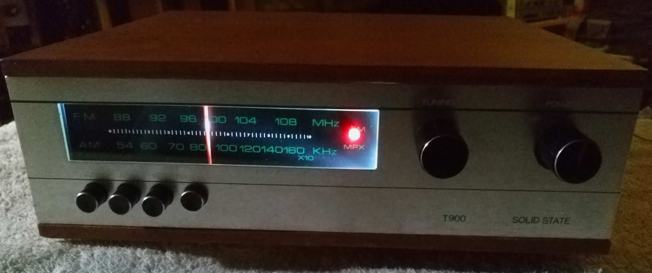
Remarks:This model was also sold under the name: Prinzsound model T-900.
The inside electronics are older and different, it has also a slightly different smaller cabinet.
This model is also from Comet Japan.
The rest of the tuner is also different inside. its with the IC in the MPX section,
The output audiostage is on the power main pcb.
The power supply is also with 1 rectifier diode.
Link to the Prinzsound model T-900 page: click here
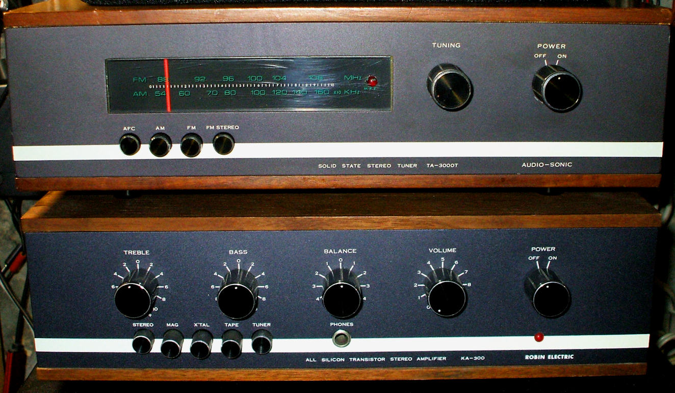
The Audiosonic tuner with the Robin as ensemble of a Comet set ^
Sound:
The sound is acceptable for this simple and vintage tuner.
![]()
![]()
© Hans Hilberink - PE1MMK ® 2003 - Last update: 24-03-2019.