|
LUXMAN
vintage
audio |
|
LUXMAN
vintage
audio |
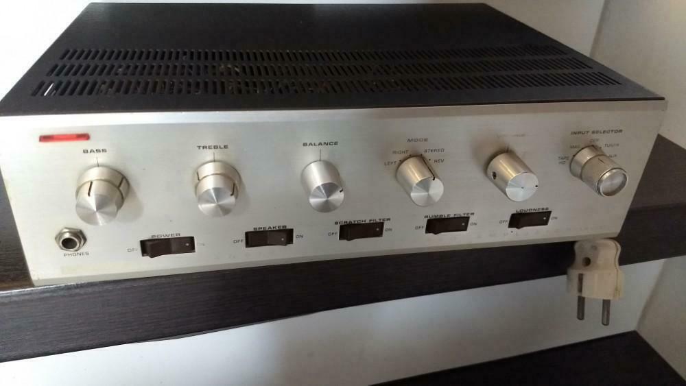
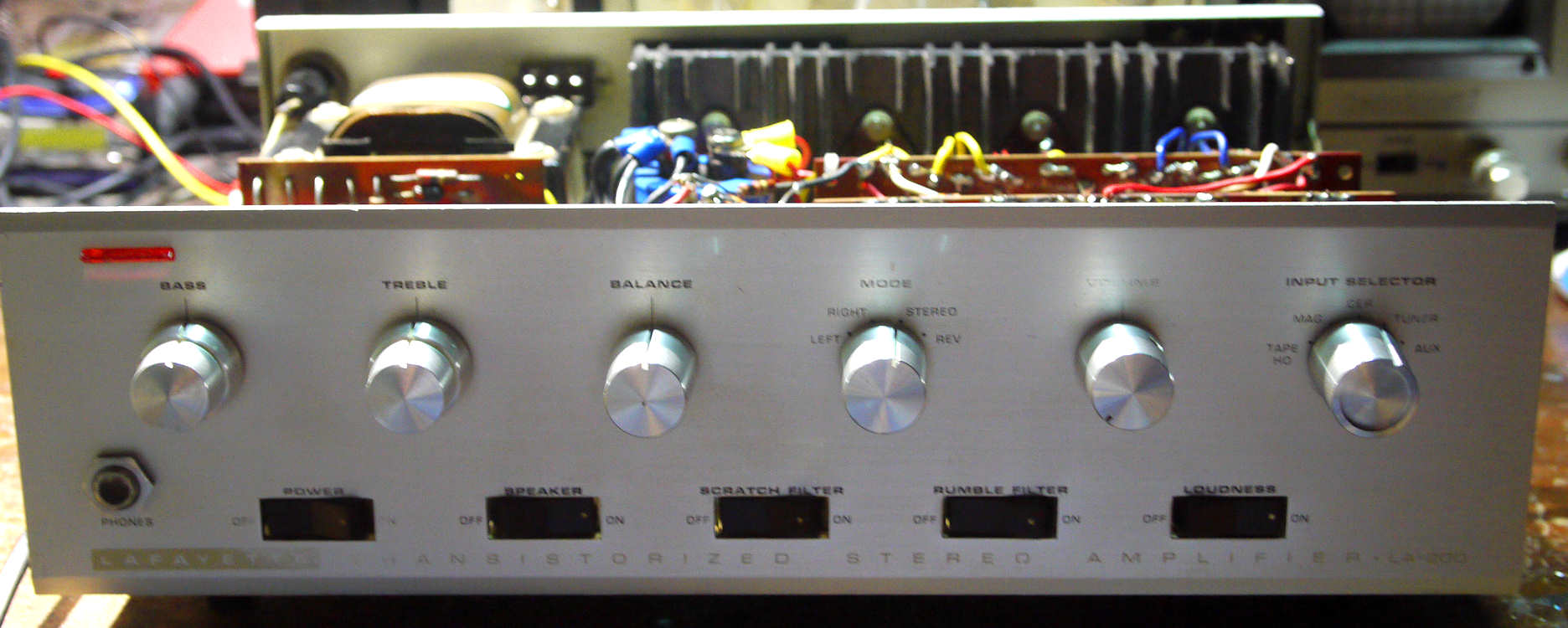
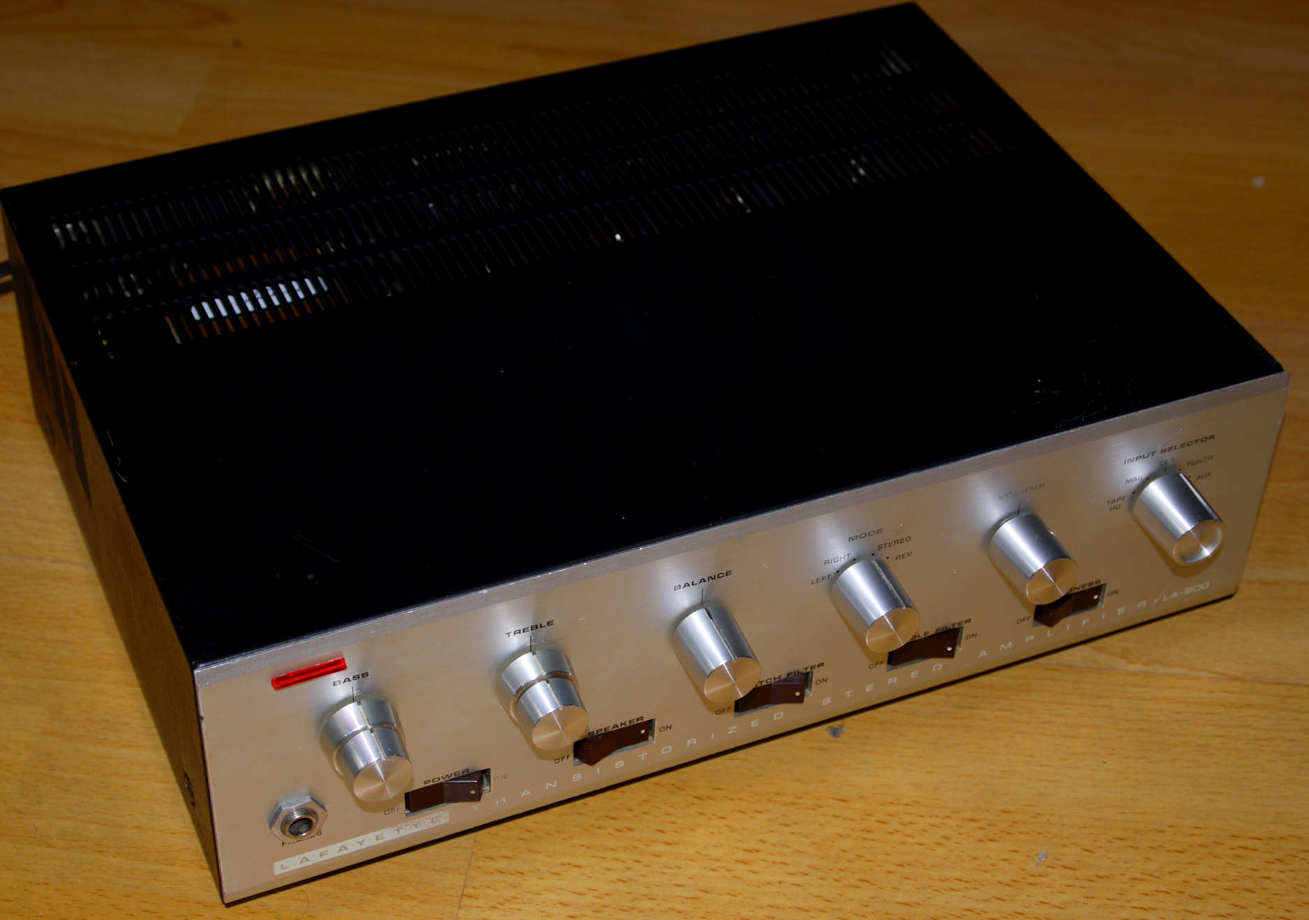
Lafayette LA-200 amplifier
General:
Around 1960/1962 issued solid-state stereo amplifier for USA markets made in Japan for LRE Lafayette.
front unrestored ^

This particular amp may be made in Japan by a subcontractor of LRE like "Planet Research" company,
and was initially bought in the UK as international version.
The Japanese subcontractors made electronic gear for more Japanese and USA companies at the time,
like Radio Shack, Heathkit, Allied Electronics and more.
Also subcontractors were: New Hope Electronics Japan with brands like "Shira",
TEC - Tokio Electronics Japan, Binatone Japan, and more.
LRE also sold Trio and Sharp electronic gear and more other brands.
Read more about LRE here: Wikipedia LRE
Owners manual:
Click here to download the user manual of the Lafayette LA-200 amplifier.
Front detail, selector knob not original^
Special futures:
This amplifier comes with cinch input sockets.
Light and compact footprint amp.
Metal case.
Well build and good parts used.
This amp employs all germanium transistors.
The pcb's of the amp are sitting vertically in the amp.
Protection circuit for power amp section.
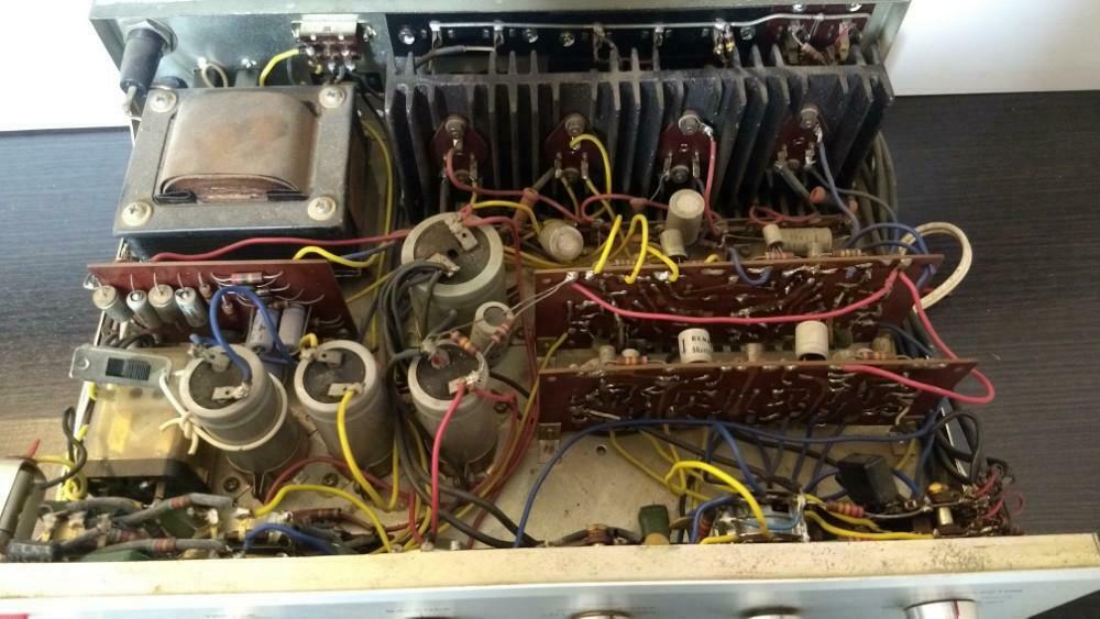
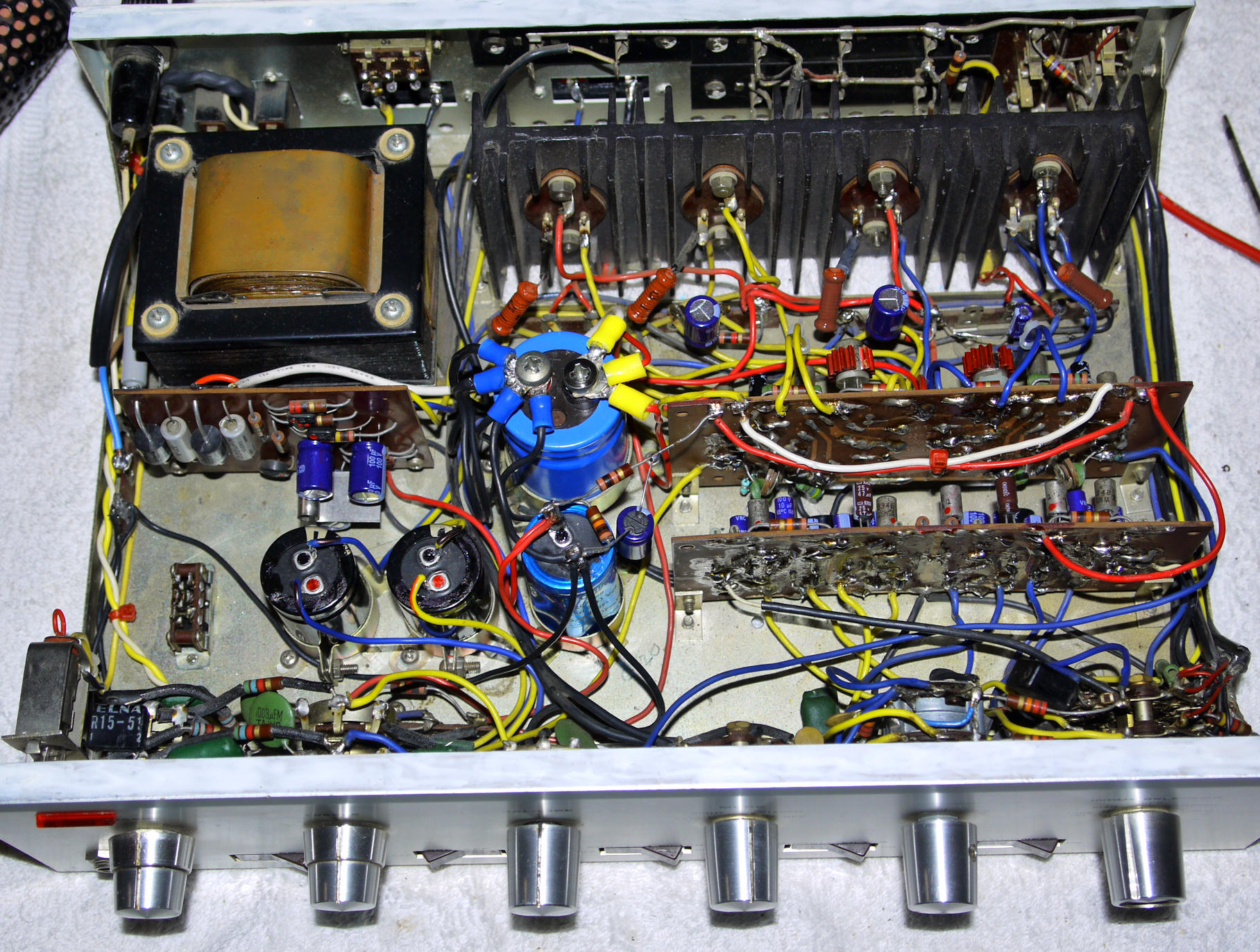
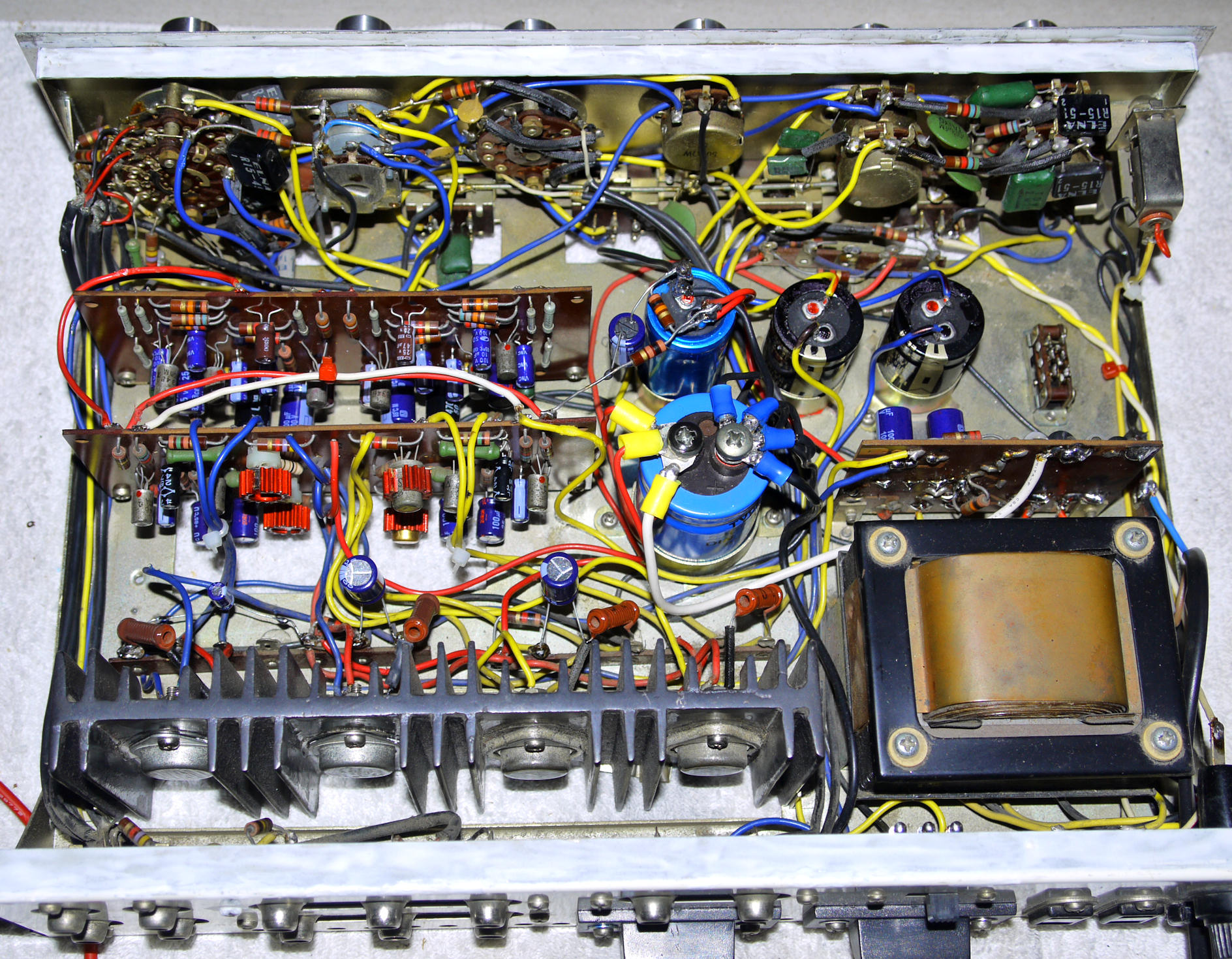
Amplifier interior unrestored: here you see a heavely used and unprofessionally repaired electronic device that needs a full overhaul ^
Specifications:
LRE Lafayette LA-200
Power output: 10 watts RMS per channel
into 8 Ohms (stereo)Frequency response: 20Hz to
20kHz +/- 3dBTotal harmonic distortion: 0.5%
at RMS outputDamping factor:
>15Input sensitivity: 2.5mV
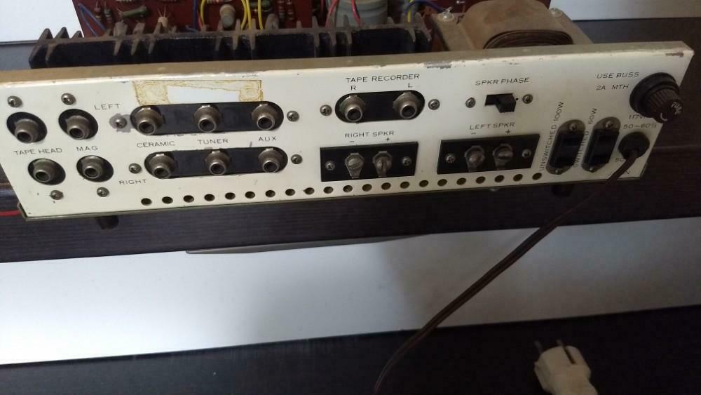
(tape head), 5mV (phono magnetic), 80mV (phono ceramic), 300mV (line)Tape-out/rec. sockets
Separated High/Low tone control L/R +/- 10 dB
Signal to noise ratio:
better than 55dB (mag), 75dB (line)Speaker load impedance: 8
to 16 Ohms (minimum)Power amp section protection circuit
Semiconductors: 1
9 x transistors, 5 x diodesSolid aluminum front plate.
Weight: 8lbs
Year: 1960-1962
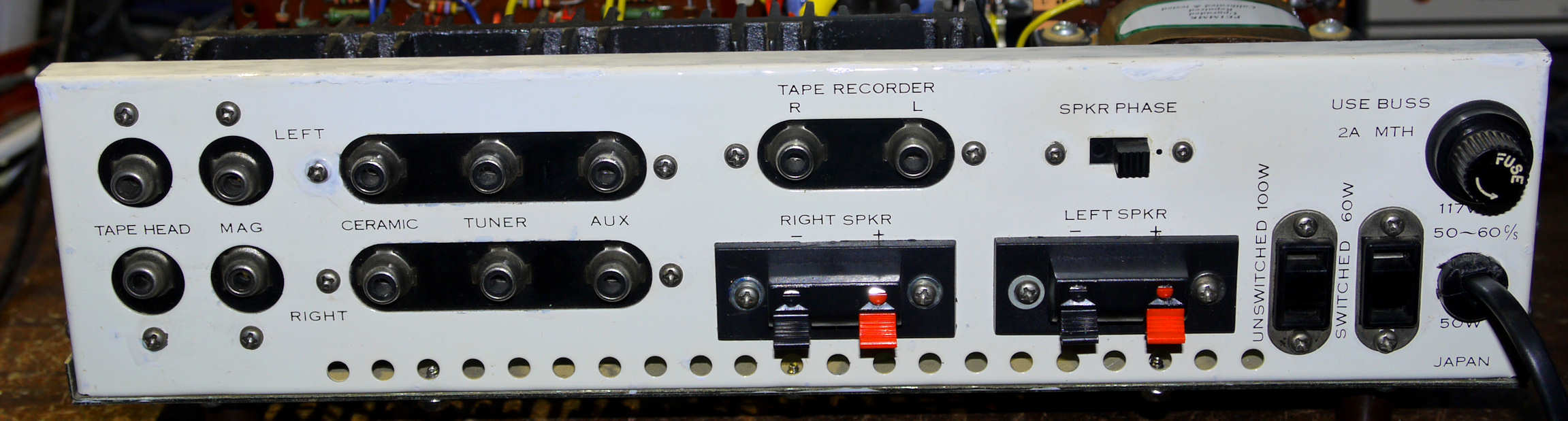
Back view unrestored ^
Pcb's from back view unrestored, here you see how unprofessional the initial repair was done: ^
like a silicon transistor soldered to the leads of the old broken Germanium NPN driver transistor,
this silicon transistor blew instantly when the amp was switched on.
Schematic:
Click here to download the schematic diagram of the Lafayette LA-200 amplifier in PDF.
Power rail main Voltage is -40 Volt asymetric, the power transformer has both 117V and 230V~ connections:
consequently due to the detrimental power change to 230V in Europe the voltage of the power rail is ok on 230V setting.
Power supply + is connected to ground.
OTL and DTL class B push-pull power amp section.
Early direct DC coupled power amp section with early Germanium driver transistors: Toshiba 2SB200 and 2SD100,
pre-driver: 2SB56. Complementary driver stage, semi-complementary power stage. The pre-amp is AC coupled.
All Toshiba & Matsusita germanium transistors inside.
This amplifier has a "power transistor protection" circuit on the power-rail pcb.
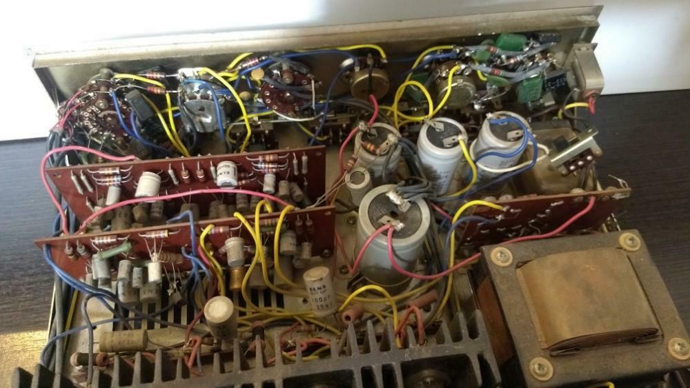
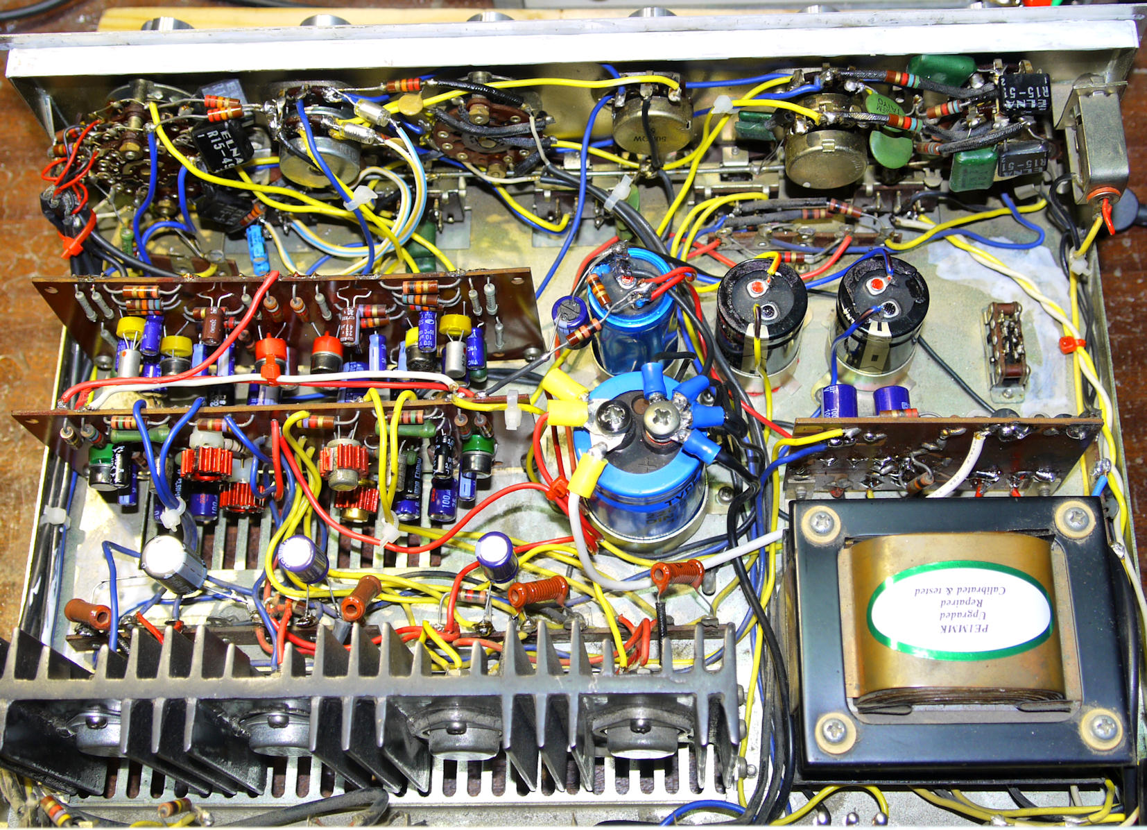
Power amp pcb's & power supply partially cleaned & restored ^
Modifications:
The 230V mains connection was completely messed up, new wiring was needed.
The power rail capacitors were leaking, cracked & broken and had to be replaced.
I replaced some diodes, capacitors and resistors in the power supply and power rail:
Sprague PS main cap, Philips PS secondary cap, Elna Gold Audio caps for the PA output stages.
Also I exchanged the speaker output screws for sockets as they were of bad quality.
On the pcb's there are some 10 special devices: consisting out of a electrolytic capacitor in combination with a resistor in one single can:
looking like a electrolytic capacitor but are NOT: used as transistor-emitter device,
I had to replace them all by a el-cap with a parallel resistor, as they were way out of specs.
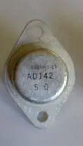
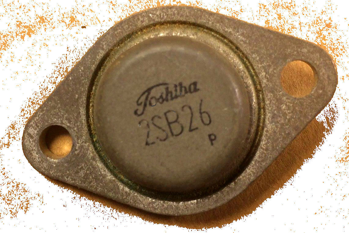
The power transistors 2SB26 were broken in the right channel, so I replaced them with AD142 as the 2SB26's are unavailable,
in the right amp the drivers 2SB200-2SD100 were broken too, replaced them too for selected 2SB383 (Sony) and 2N1304 (Ti),
as the original transistors are unavailable too. This works fine. Check DC offset after repair, set to approx.19V with VR301.
You may also use AD166 (Siemens), AL102 (Ates), 2SB337 (Hitachi), AD149(K)(H)(D) (Philips, Valvo), AD150(H) (Siemens),
or any usable TO-3 germanium transistor as 40V Uce power transistors.
The pre-amp sections all have 2SB346 and 2SB348 Matsusita transistors used.All Matsusita pre-amp transistors did not meet the specs anymore and had to be replaced,
one of the input transistor 2SB346 of the R-channel power-amp section, had a ß of 1,
and was intermittent and did not amplify anymore, but attenuated the input signal, initially the ß should be 95.
The first input transistors 2SB348, you may use AC126 (Philips, Norelco, Valvo) as replacement, this is a LN version of the AC125.
This Lafayette LA-200 amp has + to ground.
The power-supply diodes were 1A 100V types by Hitachi, these were replaced by 10A 500V general purpose diodes.
The already "star" grounding topology should be extended by 2 wires at least, to complete the grounding as it should be.
Also the power line - leads (red) should be extended by 1 wire to get the power rail right.I ommitted the mains switch 117 - 230 V as in Europe this switch will never be used.
Also the speaker-polarity switch as it is not of any use today.
I left both switches in the amp.The "power transistor protection" circuit works great, it stops the power amps from amplification of the signal actively,
when the amp is over its power capabilities. If it protects the power transistors? probably, but not in all situations obviously,
as there are many causes that can destroy the amps final transistors, overdriving the amp is only one.
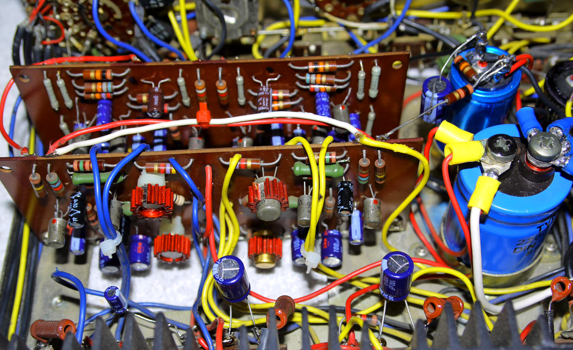
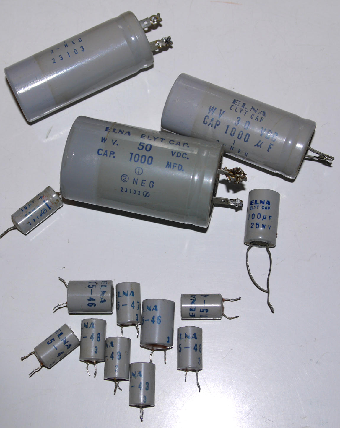
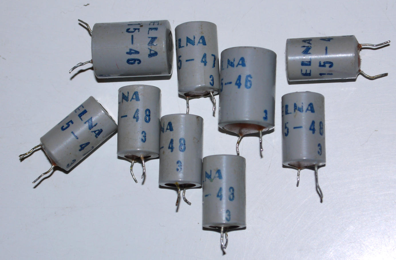
Electrolytic capacitors replaced, the old do not meet the specs anymore. But 15-46, 15-48??? what it means??? read on below. ^
^ These show like electrolytic capacitors, but they are not: High integration did not start in the 1980's: it started already in the 1960's.
These rare "look alikes" * are transistor-emitter integrated devices, yes really they are:
consisting out of a resistor and a capacitor, complete with clue-less print on the can,
no indication on the schematic diagram what 15-48 may mean and what the lead indication 1 & 3 means,
luckely on the schematic diagram Lafayette issued, the consisting parts are indicated and not the devices themselves.
So the repair was easy to do adding a resistor on the copper side of the pcb's at every emitter-device's place, as you can see on the photo.
* These parts were quite commonly used in the 1960's electronic world.
These particular were made by Elna, but there were also other manuafacturers like Sanyo, Sanken, Nikko etc.
Elna stopped quite early with production of this kind of electronic parts,
since the company recognized that the incorporated electrolytic caps deteriorated quite fast.
Other companies like Sanyo kept on improving this kind of products and later came with ie. the famous STK-module series.
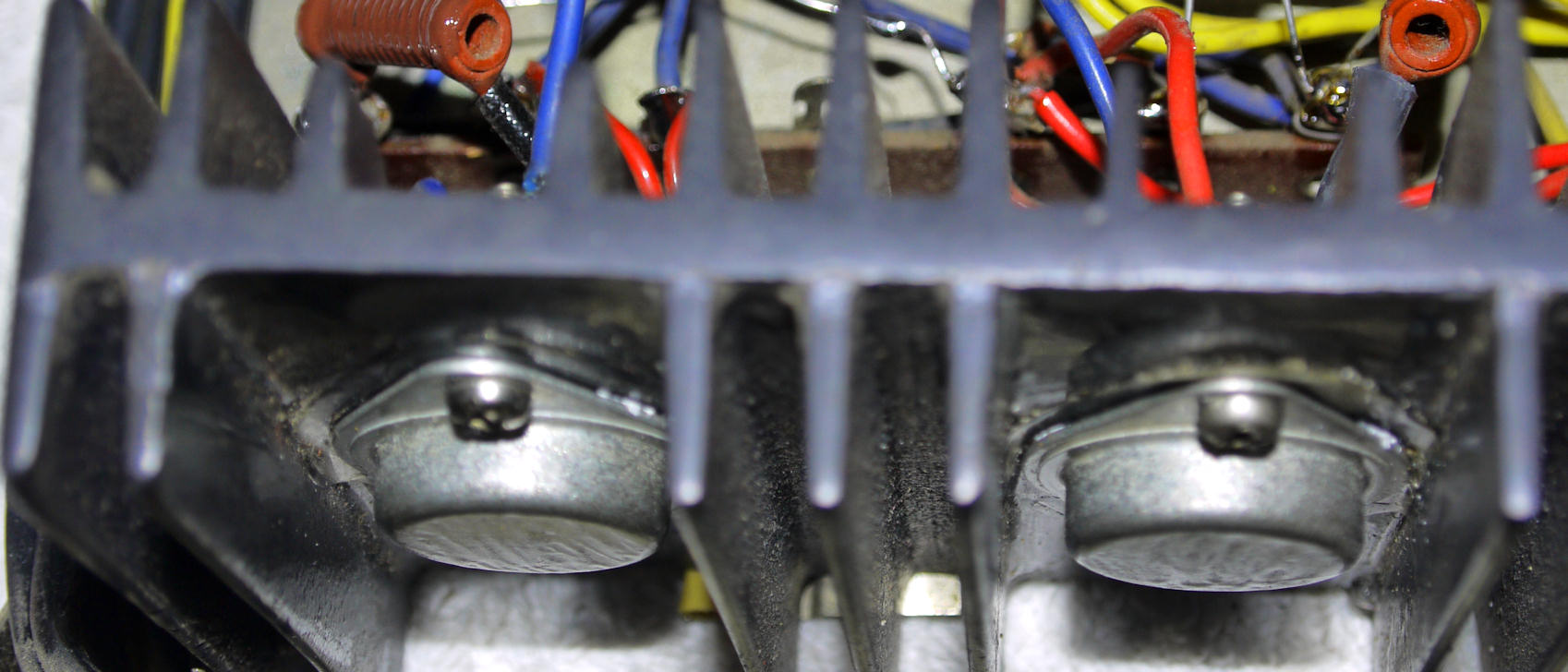
Germanium power transistors AD142 Ates SGS Italy, Uce 42V version, (repair) ^
Original power transistors are: 2SB26 Toshiba Japan. v
Testing after partially restored........ ^
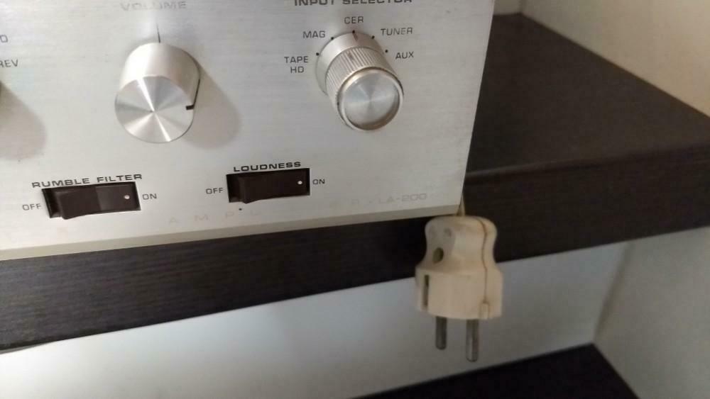
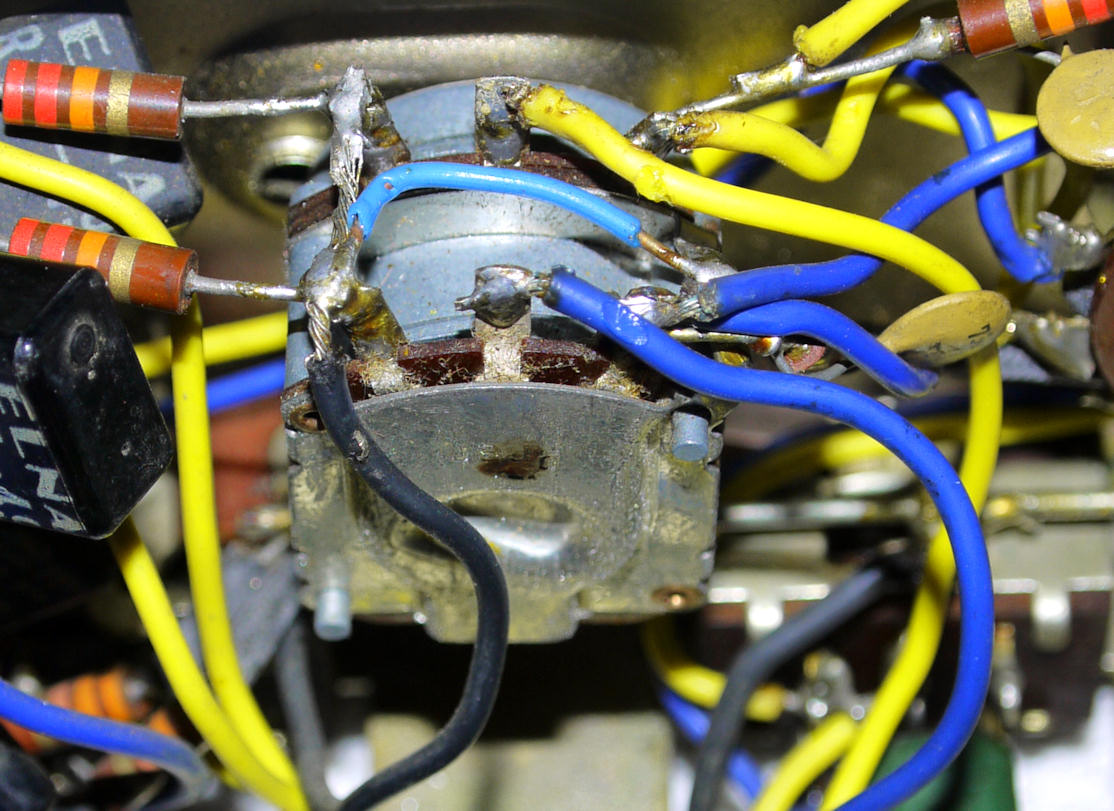
The volume-pot had been exchanged at an earlier repair: a unprofessional service attempt,
the pot they used is of German make (Preh) and not fit to be used in this amp: the Loudness-switch was disconnected during this repair.
This pot lacks the 4th connection for the Loudness connection. Also the soldering attempt is a failure.
I exchanged the wrong pot for a Japan make pot with the 4th Loudness connection on it,
and making the Loudness-switch functional again by adding wiring and the disappeared 2x 1000 pF caps, as seen on the photo's below.
Restore almost complete inside amp, exchange of pot is now one of the last things to do ^
Ready: new volume-pot, extra caps & wiring: (same wire-colouring respected), Loudness switch works great, sound is perfect. ^
Driver transistors heatsinked.
The restored back panel. ^
Front restored ^
Great product made in Japan, this amp will play fine again for many years to come ^
Sound:
The sound is very good: powerful and distortionless, considering it is an early 1960's 2x 10 Watts RMS transistor integrated amplifier.
Presented to you by ON9MMK on:
The
![]()
![]()
© Hans Hilberink - PE1MMK - ON9MMK ® 2001 - Last update: 19-08-2019.