|
LUXMAN
vintage
audio |
|
LUXMAN
vintage
audio |
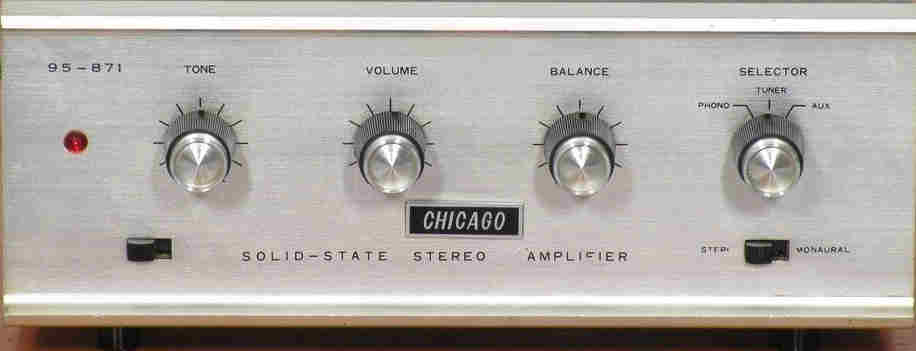
Chicago 19-350 Amplifier
General:
Integrated amplifier made in Japan around 1966/1968, with use of germanium transistors, capable of plus 10 Watts per channel
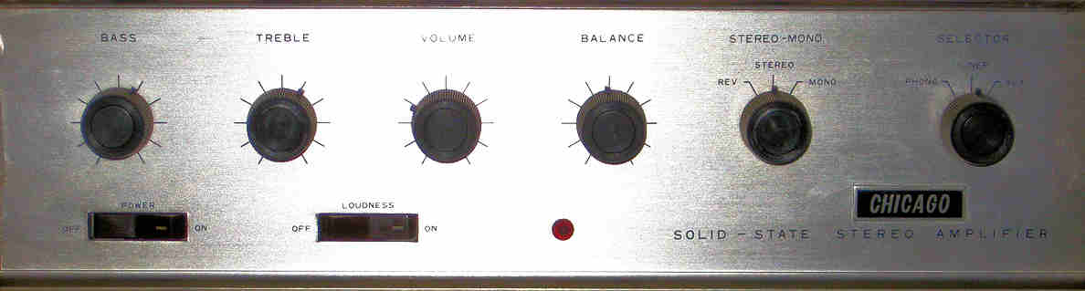
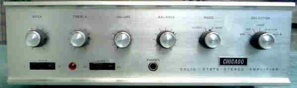
The front of this amp is the usual mainstream model as as used in most amps in these days. The front is made of solid aluminium.
The silver coloured caps on the knobs are missing.
Good cleaning is stage one of the restoration of this amp.
Owners manual:
Download the usermanual of this kind of amp here, 70 Watts version.
Download the usermanual of this kind of amp here, 25 Watts version.
special futures:
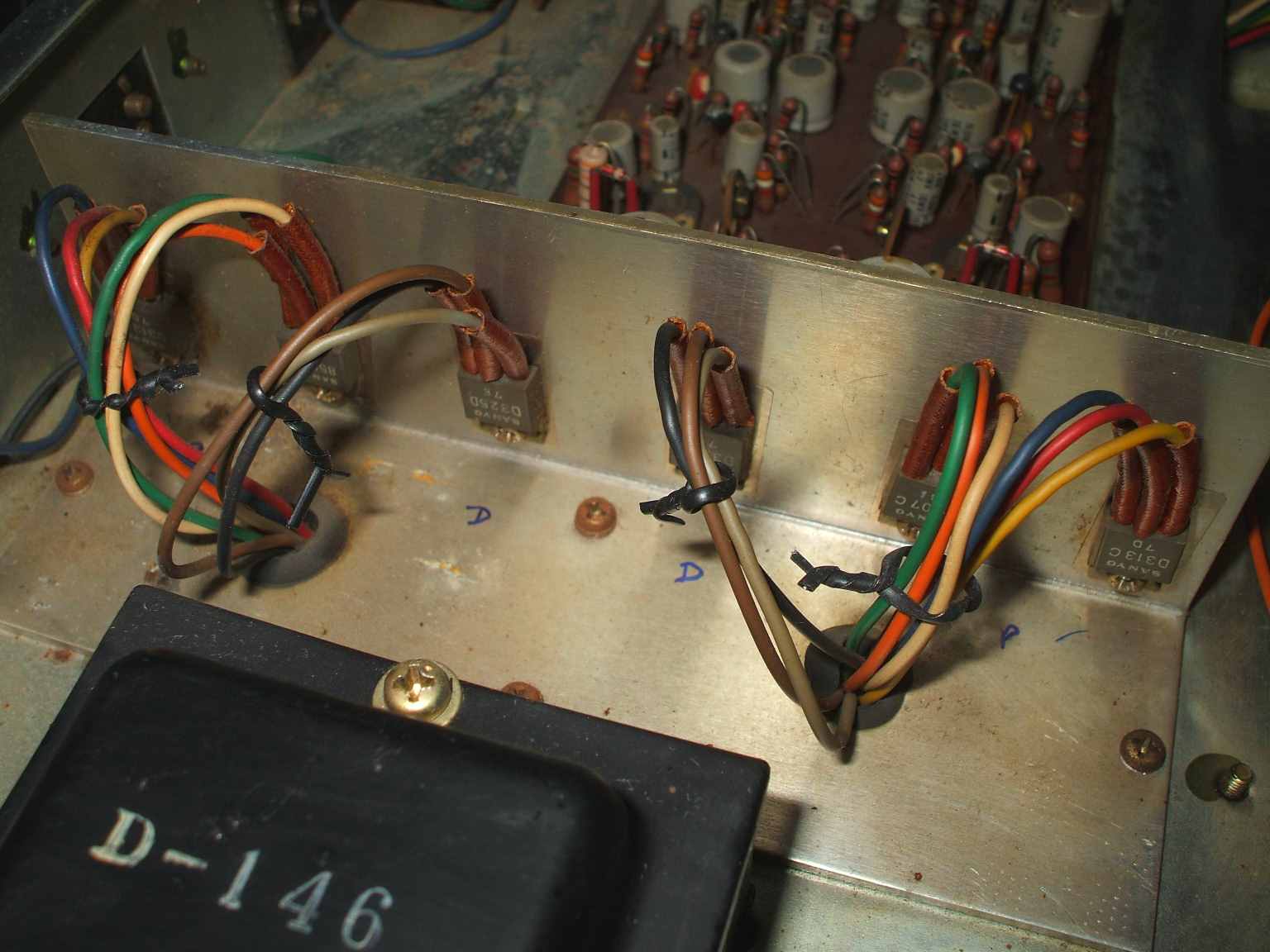
This amp has all germanium transistors made by Sanyo Japan and Ates Italy, that may be part of a repair of this amp.
The power transistors are 2SB424 up to 2SB407, 2SB 426, or replacements AD142, depending on the output power
and all other transistors are low power / low noise Sanyo 2SBxxx. The Ates AD142 transistors do their job very well in this amp.
Other types of final power transistors were used also, like the 2SB337.
At the time this was a relatively cheap amplifier, costing less than its competitors with great well known brand names like Luxman.
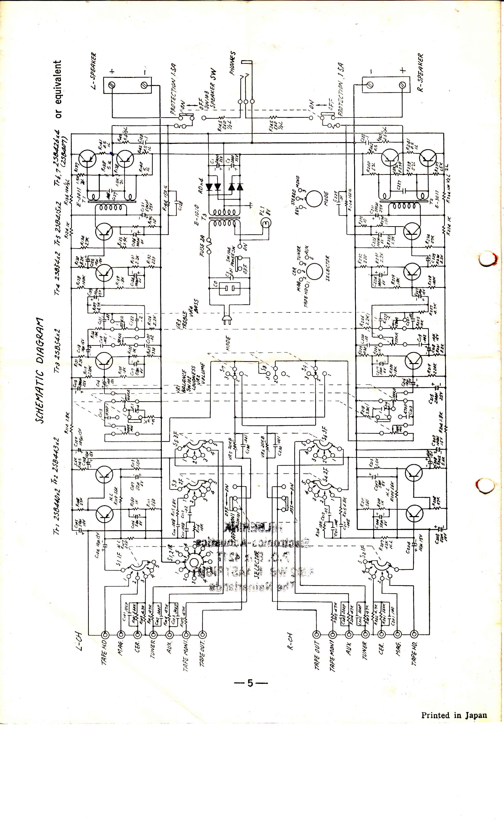
Schematic:
Schematic diagram of this kind of amp download here, 70 Watts version.
Schematic diagram of this kind of amp download here, 25 Watts version.
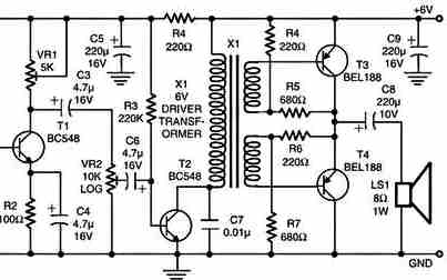
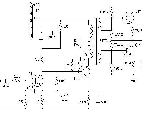
Below some basics diagram examples of this amplifier, the actual schematic diagram is slightly different,
this is shown to point out the use of a driver transformer and a OTL - OCL output stage.
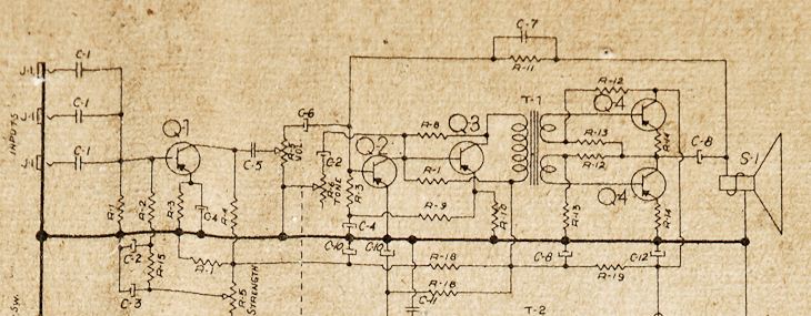
Another example of this kind of schematic diagram here: V
Another example of this kind of schematic diagram here: (part from tonegems.com) V
This amplifier may have been sold under different brand names. If you know another brandname, let me know.
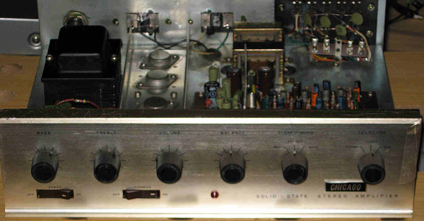
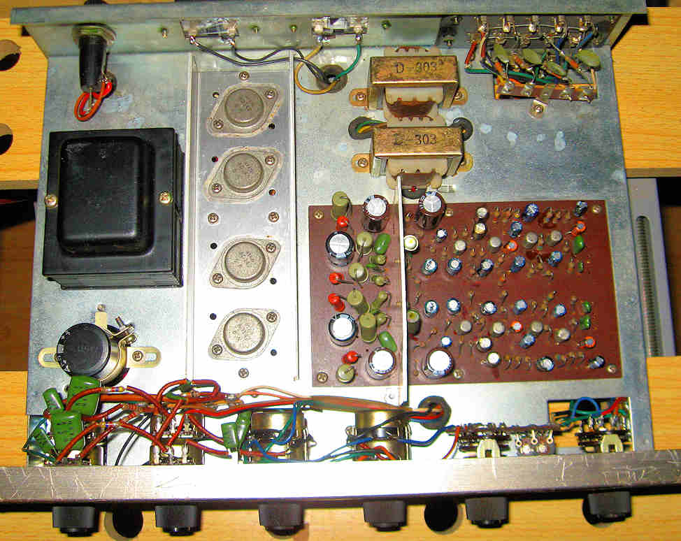
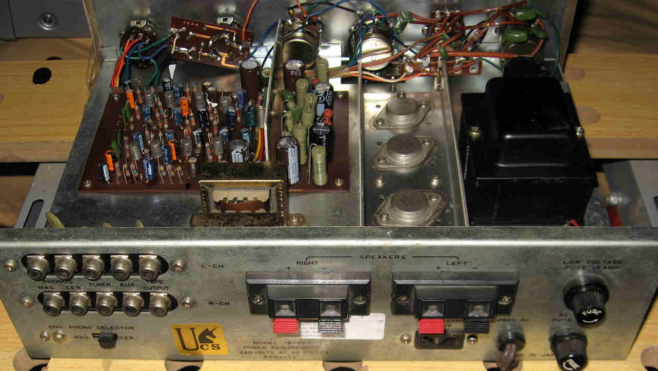
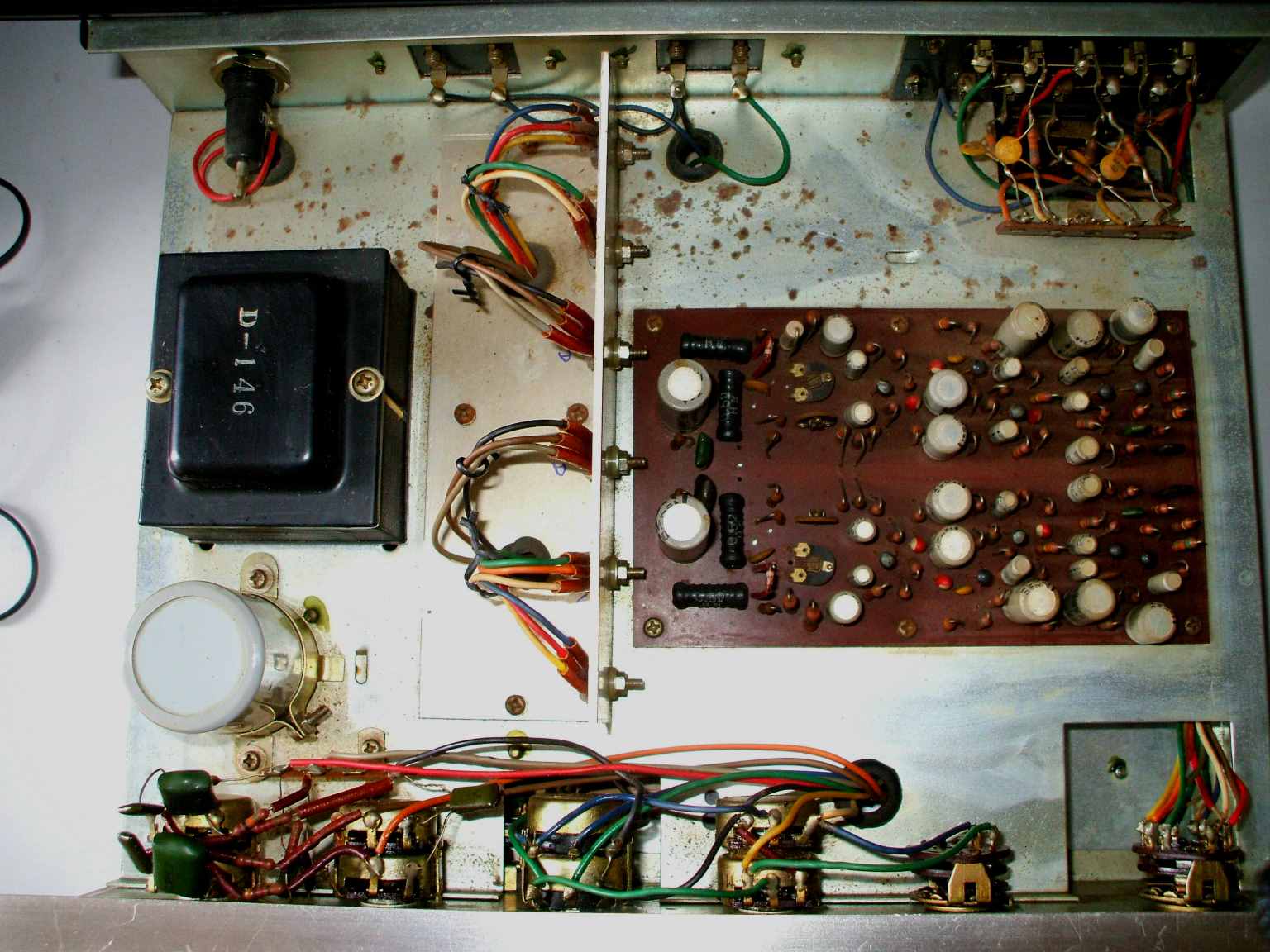
Here you can see the internals of the amp, its well built following traditional practises and the driver transformers have a prominent place inside.
All parts are still working and in good order after so many years, only the electrolytic caps need to be replaced.
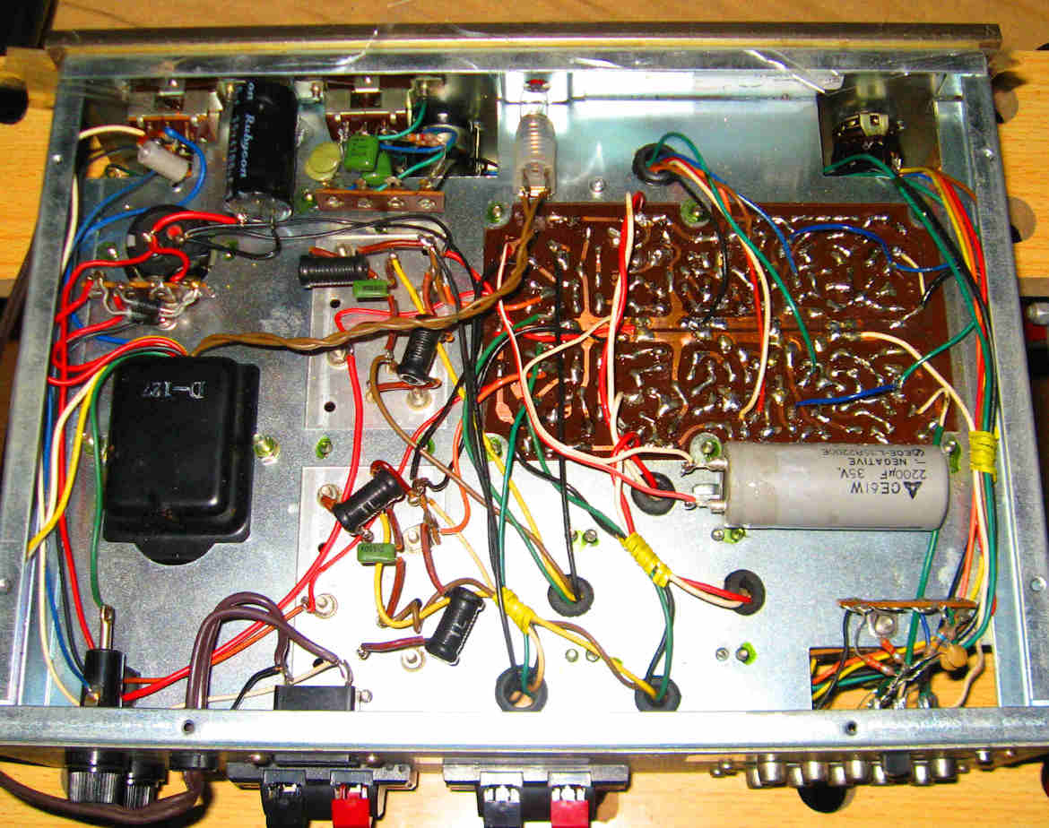
Replacing the power main and all signal path capacitors, the modern ones are of higher voltage, better quality and a lot smaller.
Using an extra capacitor in the main power section and changing the chassis wiring into "star" topology (positive + power terminal to chassis),
this makes the amp better in low frequency performance and low noise.
Modifications:
Replace all electrolytic capacitors in the power supply and power rail as shown here and all in the signal path, use SQ or LL versions on critical places.
Tighten all screws, as they may have loosening after many years of service. Replace all parts that are broken or worn out.
Check all voltages and currents in idling and dynamic working situation.
The new speaker connection terminals, the old ones were worn out. V
Below a newer version of this Chicago amplifier. It has all silicon transistors inside and has a complementary power stage, the power rail is still assymetric.
Also a 5 way input selector + a European DIN tape input and a headphones jack is added. The setup of this amp is quite the same as you can see.
The power transistors: 2SD325 drivers and 2SD313 + 2SB507 final stage.
And here another smaller, lower powered and simpler version:
Sound:
The sound is remarkably good for such an early vintage transistor amplifier, notwithstanding the old noisy germanium transistors in the pre-stages,
this is a good quality 10 Watts/ch capable power aplifier.
![]()
![]()
© Hans Hilberink - PE1MMK ® 2003, Last update: 16-11-2014.